DIN Rail Splice Boxes for Industrial Applications
DIN Splice Box, TH35 Distribution Frame, Industrial Fibre Optic: Complete Guide to Modular DIN Rail Installation in Industrial Applications
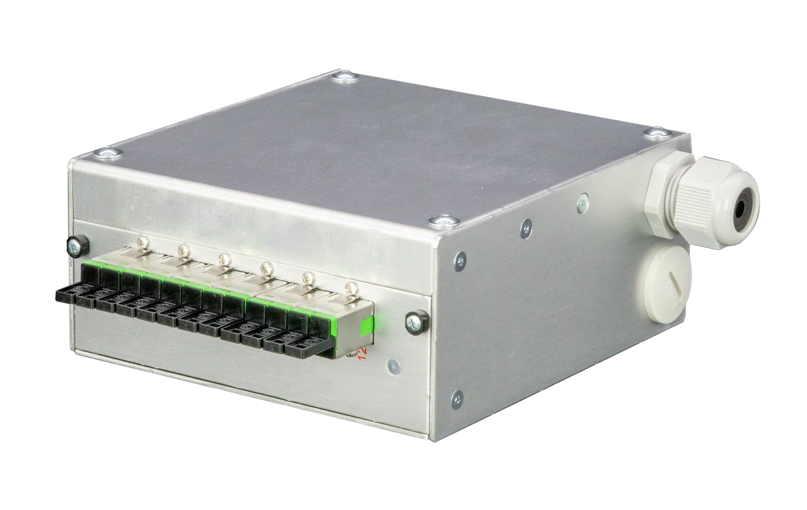
DIN splice boxes, TH35 distribution frames and industrial fibre optic components enable standards-compliant installation of optical fibres directly in control cabinets according to DIN EN 60715. Standardised DIN rail splice boxes featuring the 35mm TH35 profile combine robust industrial durability with high fibre density, establishing the technical foundation for reliable fibre optic connections in automated manufacturing environments.
Industrial system builders face the challenge of seamlessly integrating fibre optic infrastructure into existing switchboard architectures. The solution lies in modular DIN rail systems that mount tool-free onto standard rail supports whilst meeting IP65 protection ratings for harsh industrial environments.
Technical Fundamentals of DIN Rail Mounting for Fibre Optic Systems
The standard DIN EN 60715 defines rail profiles with a standard width of 35 millimetres as universal mounting elements for electronic and optical modules. In the fibre optic sector, 7TE modules (122.5mm width) have become the industry standard, offering an optimal balance between compactness and handling.
- TH35-7.5: Standard profile with 7.5mm height for normal loads
- TH35-15: Reinforced profile with 15mm height for heavy modules
- Pitch spacing: 17.5mm for precise module positioning
- Materials: Galvanised steel or aluminium for EMC-critical environments
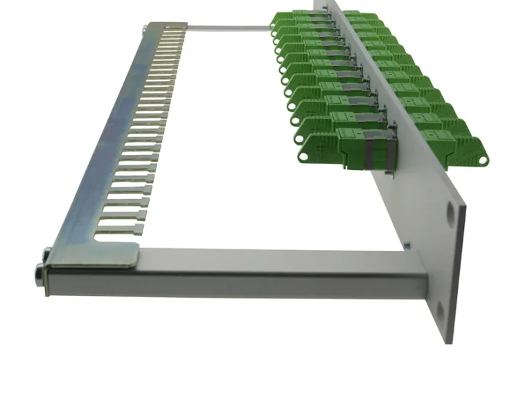
Mechanical fastening is achieved via spring clamps or screw clamps, with modern splice boxes such as the RailConnect series using tool-free snap locks. These enable installation times of under 30 seconds per module.
Step-by-Step Installation Guide for DIN Splice Box and TH35 Distribution Frame
Phase 1: Cabinet Preparation
Correct positioning of the DIN rail fundamentally determines the accessibility of fibre optic modules. Plan for a minimum 150mm clearance between the rail and the cabinet front panel for comfortable cable routing.
| Component | Minimum Clearance | Recommended Clearance |
|---|---|---|
| Cabinet top edge | 100mm | 150mm |
| Side panel | 50mm | 80mm |
| Between module rows | 120mm | 200mm |
Phase 2: Installation of Fibre Optic Rail Modules
Installation of DIN-Rail Fibre Boxes: Industrial and Automation Case Studies follows four defined work steps:
- Step 1: Position modules at 45-degree angle to the rail
- Step 2: Insert top snap edge and press downward
- Step 3: Wait for audible engagement of spring clamp
- Step 4: Perform pull test with 50N force
Fiber Products Quality Promise: As an official Diamond partner and manufacturer, we produce Splice Modules: What Professionals Consider When Selecting Systems in Europe. Benefit from Swiss precision and 5 years warranty on our DIN rail boxes and industrial modules.
Cable Entry and Strain Relief to Industrial Standards
Proper cable entry protects sensitive fibres from mechanical stress. DIN splice boxes use M20 cable glands with integrated strain relief for cable diameters from 6 to 14 millimetres.
Critical is compliance with minimum bend radius of 30mm for singlemode and 25mm for multimode fibres. Modern TH35 distribution frames integrate cable routing channels that automatically ensure the correct bend radius.
- Use only halogen-free cable entries per EN 45545-2
- Verify IP65 sealing class when gland is fully tightened
- Reserve slack of at least 1.5 metres per fibre
- Apply cable ties every 300mm for fixation
Splice Organisation in the Rail-Mounted Box
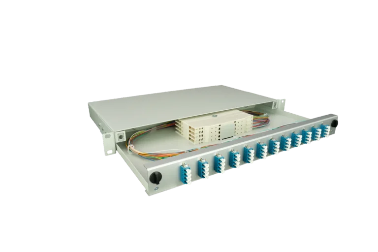
Splice Box with Integrated Cable Management determines long-term maintainability of the installation. Industrial fibre optic modules offer integrated splice trays with 24 to 48 splice storage positions per module.
| Module Type | Splice Capacity | Connector Ports | Height |
|---|---|---|---|
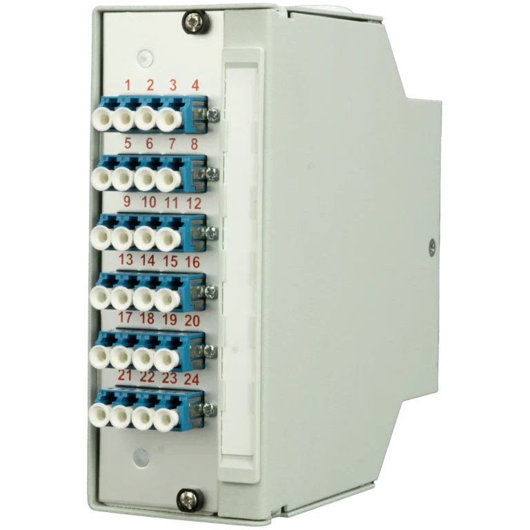
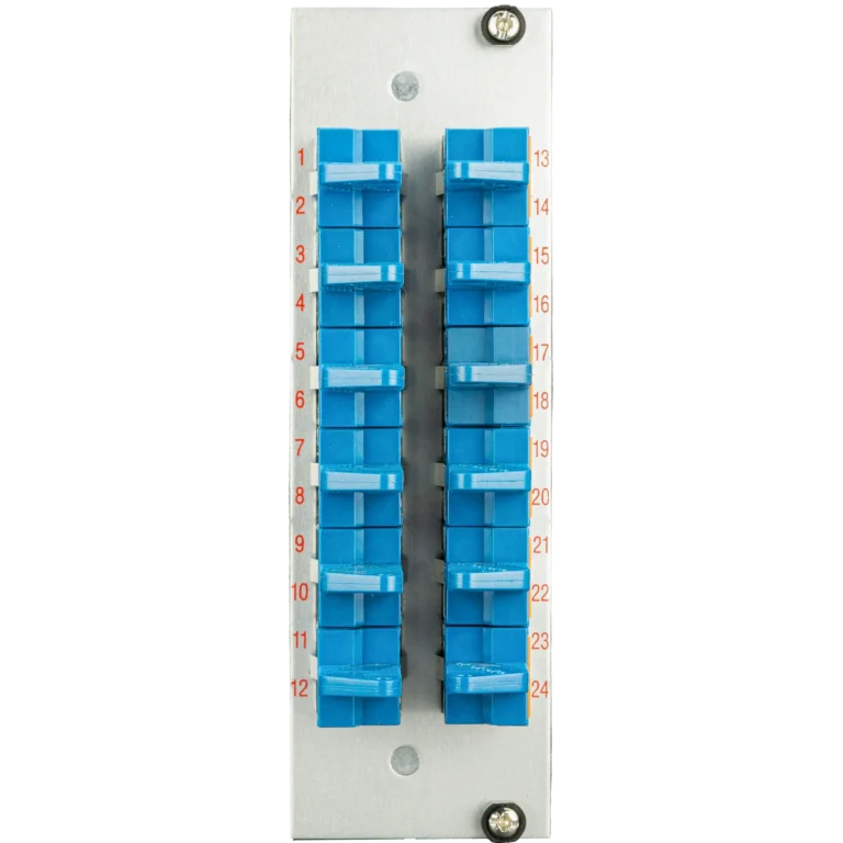
| RailConnect 24 | 24 splices | 12x LC-Duplex | 7TE |
| RailConnect 48 | 48 splices | 24x LC-Duplex | 14TE |
| SlimConnect Rail | 96 splices | 48x LC-Duplex | 21TE |
Connector Configuration for Various Industrial Applications
The choice of connector type depends on the specific application. For DIN splice box installations, three connector types have become standard:
LC Connectors for Maximum Port Density
With only 1.25mm ferrule diameter, LC connectors enable the highest packing density. A 7TE module accommodates up to 24 LC-Duplex ports, ideal for modern fieldbus and Ethernet-based automation protocols.
SC Connectors for Legacy Systems
The robust SC connector with 2.5mm ferrule dominates in older industrial installations. The SC/APC variant with 8-degree angled polish reduces reflections by up to 60dB.
E2000 Connectors for Maximum Reliability
The E2000 standard with automatic protective cap prevents contamination in dust-laden environments. As a Diamond partner, Fiber Products offers the complete E2000 product range with attenuation values below 0.1dB.
EMC-Compliant Installation in Electromagnetically Noisy Environments
Industrial environments with frequency converters, welding systems and high-voltage equipment require special protective measures. TH35 distribution frames made of metal provide inherent EMC protection through shielding.
- Ground the DIN rail via 16mm² copper conductor
- Ensure potential equalisation between all metal components
- Maintain minimum 200mm distance from high-current cables
- Use armoured fibre optic cable in critical areas
Testing and Acceptance of DIN Splice Box Installation
Standards-compliant acceptance of an industrial fibre optic installation requires optical attenuation measurements per IEC 61280-4-1. Modern OTDR test sets automatically document all relevant parameters.
| Test Parameter | Singlemode Limit | Multimode Limit |
|---|---|---|
| Splice attenuation | < 0.1dB | < 0.15dB |
| Connector attenuation | < 0.25dB | < 0.35dB |
| Return loss | > 45dB (APC) | > 35dB (PC) |
Maintenance and Troubleshooting of Rail-Mounted Modules
The modular design of DIN splice boxes significantly simplifies maintenance. Faulty modules can be replaced without interrupting neighbouring systems – a decisive advantage for continuous production processes.
Typical failure modes and remediation:
- Elevated attenuation: Clean connector end faces with isopropyl alcohol and lint-free cloth
- Total signal loss: Check bend radius, locate kink locations
- Intermittent faults: Dampen vibrations, re-tension modules
- Reflection peaks: Verify correct seating of APC connectors
Integration into Industry 4.0 Architectures
TH35 distribution frames form the physical interface between IT and OT (Operational Technology). Seamless integration of industrial fibre optic systems into existing automation architectures requires thoughtful network planning.
Modern manufacturing facilities use DIN splice boxes as decentralised distribution points for:
- Time-Sensitive Networking (TSN) with latencies below 1ms
- OPC UA communication between controllers
- Profinet over fibre for EMC-immune transmission
- 5G campus networks with fibre optic backhaul
Cost Optimisation through Pre-Terminated Systems
Pre-terminated rail-mounted modules reduce installation time by up to 60 percent. Factory termination under clean room conditions guarantees consistent quality with documented measurements for every single connection.
As a manufacturer of modular systems, Fiber Products offers custom pre-termination for industrial projects. The 5-year warranty on all rail-mounted boxes underscores the longevity of systems manufactured in Europe.
Frequently Asked Questions about DIN Splice Box Installation
Which DIN rail size is suitable for fibre optic modules?
Standard TH35 rails to DIN EN 60715 with 35mm width are optimal. For heavy modules over 500g, the reinforced TH35-15 design with 15mm profile height is recommended.
How many fibres fit in a 7TE rail-mounted module?
Depending on connector type, a 7TE module accommodates up to 24 LC-Duplex (48 fibres) or 12 SC-Duplex (24 fibres). SlimConnect technology enables up to 96 fibres in compact form.
What is the minimum bend radius for industrial installations?
For singlemode fibres, the minimum bend radius is 30mm, for multimode 25mm. In vibration-prone environments, these values should be increased by 50 percent.
Are special tools required for installation?
Modern TH35 distribution frames with snap locks require no specialist tools. Only for cable entry are wrenches of size SW27 needed for M20 glands.
How is grounding of the rail-mounted modules achieved?
Grounding is via the metallic rail itself, connected with at least 16mm² copper conductor to the protective earth. Additionally, modules feature separate grounding terminals.
What protection rating do DIN splice boxes achieve?
Closed rail-mounted boxes achieve IP65 when all cable glands are properly installed. Open modules within the cabinet typically achieve IP20.
Summary and Next Steps
Proper installation of DIN splice boxes, TH35 distribution frames and industrial fibre optic components forms the foundation of future-proof industrial automation. Adherence to the installation guidelines described ensures trouble-free operation for decades.
For your specific requirements, the fibre optic specialists at Fiber Products are available for consultation. With expertise as a Diamond partner and in-house manufacturing in Europe, we realise tailored DIN rail solutions for your industrial application. Contact us for project-specific advice on modular splice systems.
All modular fibre optic components are available directly in the Fiber Products Shop – with 5 years manufacturer warranty.
Request Expert Consultation
Our experts will advise you on modular fibre optic solutions for your specific application – fast, personal and with no obligation.