Fibre Optic Tensile Strength and Compression Load: Standards for Civil Works and Installation
The fibre optic tensile strength standard, optical fibre compression load and fibre optic mechanical stress define critical limit values for installation: fibre optic cables withstand 600 to 2700 N tensile force during installation and 2000 N/10cm compression load depending on cable type, according to DIN VDE V 0800-740. The new VDE guidelines 0800-730 and the forthcoming V 0800-735 standardise practical test procedures for microducts and splice modules in civil works installation for the first time.
For installation companies, compliance with mechanical load standards means the difference between decades of trouble-free operation and costly rework. Particularly during Germany’s current FTTH rollout wave with over 24 million premises targeted, installers must know the permissible forces precisely.
Normative Foundations of Fibre Optic Tensile Strength and Optical Fibre Compression Load according to VDE
The DIN EN 50173 standard forms the foundation for mechanical load testing of optical fibre cabling. It defines three critical phases of mechanical stress:
- Installation phase: Short-term tensile force up to 2700 N on reinforced outdoor cables
- Operational phase: Sustained tensile load maximum 1/3 of installation force
- Storage: Compression strength 2000 N/10cm at temperatures from -25°C to +70°C
The new VDE V 0800-740 specifies compression testing for microducts using a standardised 100mm test stamp. This standard fills an important gap, as over 60% of all fibre optic damage occurs during microduc installation.
| Cable Type | Max. Tensile Force Installation | Max. Tensile Force Operation | Compression Load |
|---|---|---|---|
| Indoor cable (simplex/duplex) | 600 N | 200 N | 500 N/10cm |
| Universal cable | 1500 N | 500 N | 1500 N/10cm |
| Outdoor cable reinforced | 2700 N | 900 N | 2000 N/10cm |
| Micro cable 2–12 fibres | 800 N | 270 N | 1000 N/10cm |
Practical Measurement Technology for Fibre Optic Mechanical Stress in Civil Works
Modern tensile force meters with digital force display and data logging function document actual load during installation. The VDE 0800-735 (in preparation) will for the first time mandate measurement intervals of 10 seconds during critical cable pulling operations.
Professional installers use calibrated measurement systems with ±2% measurement accuracy according to DIN EN ISO 7500-1. These devices capture not only peak values but also load duration – a critical factor for long-term fibre stability.
- Tensile force limiters: Mechanical safety at 80% of maximum load
- Pressure measurement plates: Load distribution to simulate earth loads
- Temperature compensation: Correction of measurements under extreme conditions
- Data logging: Complete documentation for warranty purposes
Critical Installation Phases: Tensile Force during Cable Pulling and Installation
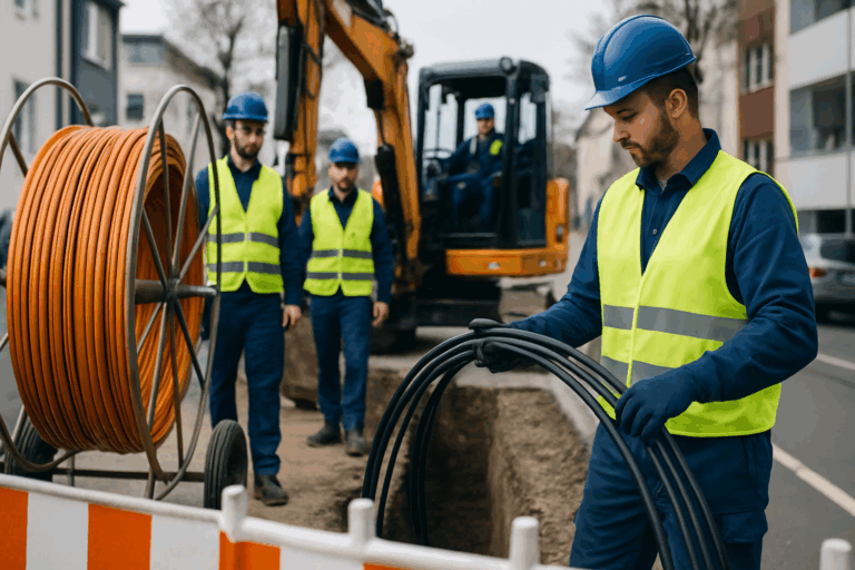
The highest mechanical loads occur when cables are pulled into conduits. At 90° bends, tensile force multiplies by a factor of 1.6; with two successive bends, by 2.5.
Modern splice modules with pre-terminated pigtails significantly reduce mechanical stress. Instead of pulling entire cable runs, only short patch sections need installation – tensile force drops.
Fiber Products Quality Commitment: As an official Diamond Partner and manufacturer, we produce modular splice systems in Europe. Benefit from Swiss precision and 5 years warranty on our systems – specifically engineered for the high mechanical demands of German civil works installation.
Compression Load on Optical Fibre: Earth Loads and Traffic Load Testing to Standard
In civil works, static and dynamic compression forces act on installed fibre optic cables. The DIN VDE V 0800-740 defines test procedures using a 100mm test stamp at 20 kN force for 60 seconds.
There is no standard that ties a cover depth to a compression strength class. The depth comes from the road authority’s rules and the network operator’s own specification for the route; the required duct and cable class is stated per project in the tender. What is technically relevant is that compaction produces short load peaks well above the static load — reinforced constructions with aramid yarn or steel armouring prove effective here.
Temperature Effects on Fibre Optic Tensile Strength Standards and Mechanical Properties
Extreme temperatures dramatically change the load-bearing capacity of optical fibre cables. At -25°C, permissible tensile force reduces by 40%, while compression sensitivity doubles.
- Winter installation: Store cables at least 24 hours at >10°C
- Summer installation: UV protection and shielding against direct sunlight
- Temperature cycling: Maximum change 30°C per hour permitted
- Operating temperature: Sustained exposure -40°C to +70°C per IEC 60794
Splice Modules and Mechanical Decoupling: Protection from Tensile and Compression Forces
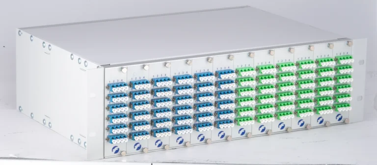
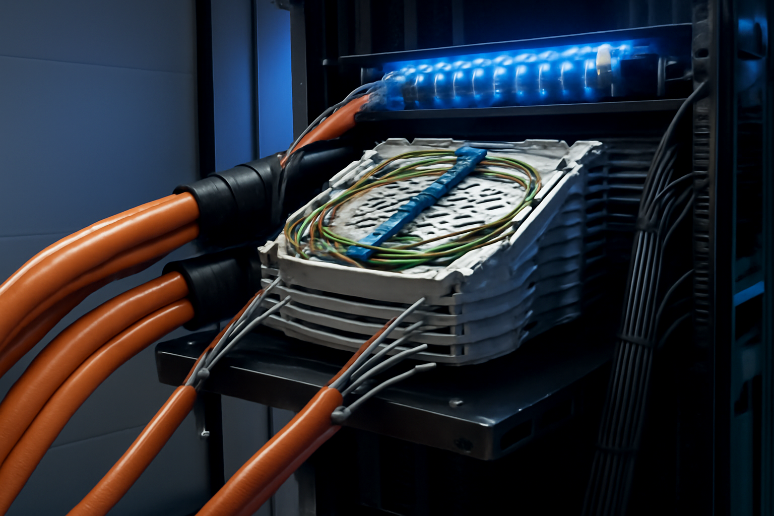
Modern splice modules such as the SlimConnect Series provide mechanical decoupling through spring-loaded cassette systems. The fibre optic mechanical stress is reduced through strain relief and slack management.
Modular design enables 96 fibres in just 1 rack unit – with complete mechanical isolation of each individual fibre. Specialised cable entries with bend protection and strain relief prevent force transfer to sensitive splice points.
Microducts and Blow-In Methods: Special Requirements for Optical Fibre Compression Load
When blowing micro cables, different forces act compared to conventional cable pulling. The VDE V 0800-735 defines maximum blow-in pressures of 15 bar with simultaneous pulling support of maximum 300 N.
Pressure spikes during blow-in machine start-up are critical. Modern equipment with soft start and pressure regulation limits acceleration to <5 m/s². The fibre optic tensile strength standard requires continuous monitoring with automatic shutdown on limit exceedance.
- Micro cable 2–12 fibres: Max. 10 bar blow-in pressure
- Micro cable 24–48 fibres: Max. 12 bar blow-in pressure
- Micro cable 72–144 fibres: Max. 15 bar blow-in pressure
- Blow-in length: Up to 2000m under optimal conditions
Quality Assurance: Documentation of Mechanical Load to Standard
fibre optic documentation is increasingly becoming mandatory in public procurement. The optical fibre compression load and tensile force records must be archived for at least 10 years.
Professional documentation systems automatically record date, time, GPS position and measurement values. Integration into digital fibre optic documentation systems enables complete traceability throughout the entire lifecycle.
Damage Prevention: Avoiding Typical Errors in Fibre Optic Mechanical Load
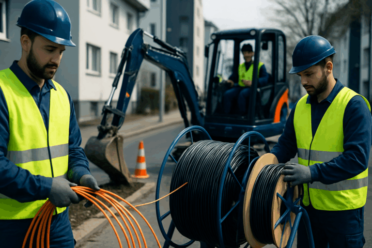
The most common damage results from disregarding the fibre optic tensile strength standard in seemingly non-critical situations. Simply improper cable unspooling can cause microcracks that lead to total failure years later.
| Error Source | Mechanical Load | Damage Potential | Prevention |
|---|---|---|---|
| Spool unwinding | Torsion + tension | Microcracks | Use cable cart |
| Tight bend radii | Bending stress >1000 N | Attenuation increase | Min. 15× cable diameter |
| Cable clamps | Point load >3000 N/cm² | Jacket damage | Large-area cable clips |
| Backfill | Impact load during compaction | Crushing | Layer-by-layer, gentle compaction |
Frequently Asked Questions on Fibre Optic Tensile Strength and Optical Fibre Compression Load
Which tensile force meters are approved for documentation under VDE 0800-735?
No standard approves specific force meters — there is no type-approval list. Good practice: use a calibrated force-measuring device whose range and resolution match the cable’s maximum permissible tensile load from the manufacturer’s datasheet (mechanical test procedures per EN 60794-1-21), and record the pulling force during installation. Calibration intervals are set by your own quality management system, not fixed by a cabling standard.
How does moisture affect mechanical load-bearing capacity?
Penetrating moisture reduces tensile strength by up to 30% through swelling of aramid yarns. Critical are damaged cable jackets – here permissible tensile force must be reduced by 50%.
Do standards also apply to pre-terminated patch cables?
Yes. EN 50173 specifies performance at link and component level, so it applies to pre-terminated assemblies just as it does to field-terminated links. Tensile load, however, is not capped per connector type: IEC 61300-2-4 is the fibre/cable retention test method, and the applicable retention load depends on the cable construction and the relevant performance standard (IEC 61753 series) — the binding figure is the one on the product datasheet.
What is the minimum installation depth for fibre optic cables?
No single standard fixes a minimum cover depth for fibre optic cables. DIN 1998 is a planning guideline for arranging services in public surfaces, not a legal basis for a depth. The depth comes from the road authority’s rules and the network operator’s own specification for the route, and reduced-depth methods such as trenching are handled under their own conditions. For cable protection ducts note that EN 61386-24 was withdrawn in 2023 and replaced by EN 50626-1 — specify the required duct class per project from the current document.
Do standards differ for single-mode and multi-mode fibres?
Mechanical load standards apply equally to both fibre types. Differences exist only in optical limit values – single-mode fibres are more sensitive to microbending, with attenuation increase starting at 15 mm bend radius.
How long can maximum tensile force be applied during installation?
Maximum installation tensile force may apply continuously for maximum 60 seconds. For longer loads, force must be reduced to 70% of maximum value. Breaks of at least 5 minutes between pulling operations are required.
Consistent adherence to fibre optic tensile strength standards and optical fibre compression load requirements protects your investment in modern fibre optic networks sustainably. With professional measurement technology and high-quality splice systems, mechanical stresses can be minimised and required network quality assured over decades.
Request a Quote
Have questions about our fibre optic solutions? Our expert team will be happy to advise you — free and with no obligation.