Fibre Optic Bending Radius: Standards and Installation Best Practices
Fibre Optic Bending Radius: Standards and Installation Best Practices
The fibre optic bending radius fundamentally determines the functionality and lifespan of optical fibre installations – for modern fibre optic cables, a minimum bending radius of 60 mm applies to permanent installations in conduits, while temporary bends during installation allow up to 30 mm radius. The optical fibre bending standard per IEC 60793-2-50 defines precise limits for singlemode and multimode fibres, with bend protection through correct bending radii ensuring attenuation increases of no more than 0.1 dB per bend.
As an installation company, you must adhere to strict bending radius specifications during fibre optic deployment to avoid signal loss and fibre breakage. The new VDE Guideline 0800-730 (February 2026) significantly simplifies installation practice and reduces assembly costs through practical specifications.
Technical Fundamentals: Why Bending Radius is Critical
When the minimum bending radius is exceeded, two critical effects occur: macrobends cause optical fibre attenuation per faulty bend, while microbends disrupt total internal reflection and cause permanent damage. The physical limit lies at a critical angle where light rays exit the fibre core.
- Singlemode fibres (OS2): Minimum bending radius 30 mm temporary, 60 mm permanent
- Multimode fibres (OM3/OM4): Minimum bending radius 15× cable diameter
- Bend-insensitive fibres (G.657.A2): Reduced radius of 15 mm possible
- Maximum tensile load: 100 N during installation, 50 N permanently
New VDE Standards 2025/2026: A Game-Changer for Installation Companies
The revised Model Directive on Fire Safety Requirements (MLAR) recognises for the first time: fibre optic cables pose no intrinsic fire hazard. This reassessment enables installation in metal ducts instead of expensive fire-rated conduits – a cost saving of up to 40 percent in building cabling.
The VDE Guideline 0800-730 defines binding standards for in-building optical fibre networks and provides legal certainty for installers. Key requirements include minimum bending radii, conduit specifications and documentation requirements for later acceptance.
| Installation Area | Minimum Bending Radius | Conduit Diameter | Special Requirements |
|---|---|---|---|
| In-building | 60 mm | Min. 10 mm | Smooth inner surface required |
| Building entry | 30–45° bends | DN 50–100 | 30 cm below ground level |
| Data centre | 30 mm | Cable trays | High-density cabling |
| Industrial environment | 10× cable diameter | Protective conduits | Vibration-resistant mounting |
Practical Installation Rules for Error-Free Optical Fibre Deployment
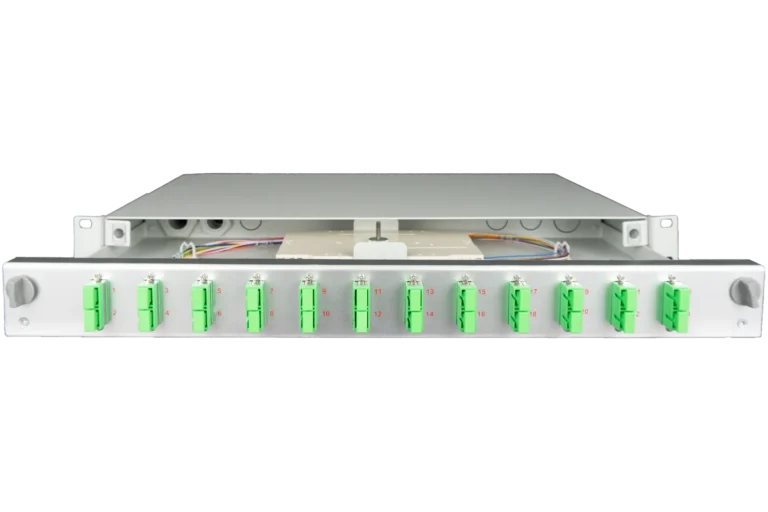
The fibre optic bending radius must be monitored throughout installation. Critical points are cable entry points, distribution cabinets and transition points to splice modules. Modern modular systems such as the SlimConnect series already account for these requirements in their design.
Step-by-Step Guide for Standards-Compliant Installation
- Preparation: Inspect conduits for burrs, use pull-in aids with radius > 60 mm
- Cable pulling: Maximum pulling force 100 N, continuous speed
- Direction changes: Lay cable freely before and after corners, no conduit bends
- Securing: Cable ties every 50 cm, without crushing
- Documentation: Record bending radii at critical points
When installing in existing buildings, tight shafts and winding cable routes present particular challenges. Here, the use of bend-insensitive fibres to ITU-T G.657 is recommended, which tolerate temporary bending radii down to 7.5 mm.
Cost Savings Through Optimised Bending Radius Planning
Correct planning of the optical fibre bending standard can achieve significant cost savings. Faulty installation with excessively tight bending radii results in attenuation losses averaging 1.5 dB per run – equivalent to a 30 percent reduction in range.
Fiber Products Quality Promise: As an official Diamond Partner and manufacturer, we produce modular splice systems in Europe. Benefit from Swiss precision and 5 years warranty on our systems.
Cost-Benefit Analysis for Installation Projects
| Cost Factor | Previous MLAR Requirement | New VDE 0800-730 | Savings |
|---|---|---|---|
| Fire-rated conduits | €85/m | Metal ducts: €35/m | 59% |
| Installation time | 45 min/floor | 25 min/floor | 44% |
| Rework | 15% of projects | 3% of projects | 80% |
Fibre Optic Bend Protection: Mechanical Protective Measures
Fibre optic bend protection begins with cable selection. Robust outer jackets with aramid yarns or metallic reinforcement protect delicate fibres from mechanical stress. In industrial environments, additional protective conduits with IP65 certification are required.
- Bend protection sleeves: Install at all cable exits
- Bend radius guides: Use as standard in 19-inch cabinets
- Cable management systems: Structured routing with defined radii
- Strain relief: At connection points for load distribution
Special Requirements for Different Installation Environments
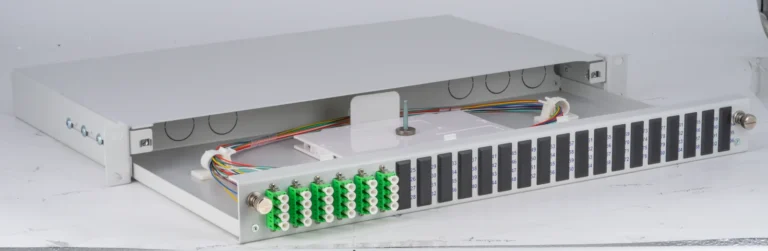
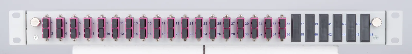
Different requirements apply to fibre optic bending radius depending on the application. In data centres with high port density, patch cables with reduced bending radii of 15 mm must be used. The VarioConnect systems offer up to 288 fibres in 4U with maximum packing density while maintaining all bending radius specifications.
Industrial Environments and Customised Solutions
In harsh industrial environments with vibration and temperature fluctuations, special protective measures are required. DIN rail-mounted boxes with integrated bend radius guides secure the optical fibre bending standard even under extreme conditions. Installation is tool-free on standard DIN rails.
Quality Control and Acceptance Testing
After installation, correct fibre optic bending radius compliance must be verified by measurement. OTDR measurements reveal attenuation peaks at locations with excessively tight bending radii. Limits per IEC 61280-4-2 must not be exceeded.
- Visual inspection: Check all visible cable runs
- OTDR measurement: Attenuation profile across entire run
- Documentation: Archive measurement records for warranty purposes
- Follow-up measurement: Recommended after 6 months of operation
Common Mistakes to Avoid When Observing Bending Radius
Despite clear specifications for the optical fibre bending standard, recurring mistakes occur in practice. The most common cause of complaints is excessively tight bending radii at wall penetrations resulting in attenuation losses exceeding 1 dB. Systematic training of installation teams and use of appropriate installation aids can prevent these errors.
As a manufacturer of modular fibre optic solutions, Fiber Products supports installation companies with practical systems. The splice modules of the SlimConnect series already incorporate all relevant bending radius requirements in their design, significantly simplifying standards-compliant installation. For further technical details, see our Fibre Optic Knowledge Portal.
FAQ: Bending Radius in Fibre Optic Installations
What minimum bending radius applies to standard singlemode fibres?
For permanent installations, the minimum bending radius is 60 mm, while during installation 30 mm is temporarily permissible. These values apply to standard OS2 fibres per ITU-T G.652.
How do I detect damage from excessively tight bending radius?
OTDR measurements reveal local attenuation peaks at affected locations. Visible signs include fibre discolouration or increased breakage during splicing. An attenuation increase exceeding 0.5 dB indicates critical bends.
Do patch cables have different bending radius requirements?
Yes, modern patch cables with bend-insensitive fibres (G.657.A2) allow bending radii down to 7.5 mm. Standard patch cables should however maintain at least 15 mm bending radius.
How do I correctly document bending radius compliance?
Create an installation record with photographs of critical points, OTDR measurement reports and details of cable types used. VDE 0800-730 requires complete documentation for acceptance.
What tools help ensure bending radius compliance?
Bending radius templates, pre-configured guide elements and cable pull-in aids with defined radius ensure standards-compliant installation. Professional cable management systems already integrate these aids.
Must I adapt existing installations to new bending radius standards?
Existing legal protection applies to functioning installations. However, extensions or modifications must comply with current standards. A re-measurement of existing runs is recommended.
Request a Quote
Do you have questions about our fibre optic solutions? Our expert team will be happy to advise you – free of charge and with no obligation.