Optical Fibre Attenuation: Measurement and Limits According to IEC 61300
Optical Fibre Attenuation: Measurement and Limits According to IEC 61300
Optical fibre attenuation, IEC 61300, optical fibre loss and dB limits are critical parameters for the quality of every fibre optic connection – the IEC 61300 standard defines exact measurement procedures and limit values of maximum 0.75 dB per connector and 0.1 dB per splice for professional installations. As a technical planner or installer, you must measure and document these attenuation values precisely to realise standards-compliant fibre optic networks. Correct application of IEC 61300 measurement procedures determines the performance of your entire fibre optic infrastructure.
Fundamentals of Optical Fibre Attenuation According to IEC 61300
Attenuation in optical fibres describes the signal loss that occurs as light passes through the fibre. This loss is measured in decibels (dB) and comprises several components: intrinsic fibre attenuation, connection losses at connectors, and splice losses.
The standards series IEC 61300 (adopted in Germany as DIN EN 61300) standardises test and measurement procedures for fibre optic components. IEC 61300-3-4 describes methods for measuring the attenuation of optical components. For installed cabling the relevant standards are IEC 61280-4-1 (multimode) and IEC 61280-4-2 (single-mode), which cover both the light-source-and-power-meter method and the OTDR.
- Single-mode fibres (SMF): 0.2 dB/km at 1550 nm
- Multi-mode fibres (MMF): 3.5 dB/km at 850 nm
- New hollow-core fibres (HCF): 0.091 dB/km (record value 2026)
- Connectors: maximum 0.75 dB per standard
- Splice connections: typically 0.05 to 0.1 dB
Measurement Methods for Optical Fibre Loss According to IEC 61300-3
IEC 61300-3 distinguishes two primary measurement methods for determining optical fibre attenuation. The LSPM method (Light Source Power Meter) measures total line attenuation by comparing injected and received optical power. This method provides highly precise absolute values with an accuracy of ±0.1 dB.
The OTDR measurement (Optical Time Domain Reflectometry) sends light pulses into the fibre and analyses the backscattered signals. This enables you not only to determine total attenuation but also to locate individual attenuation events – ideal for troubleshooting in complex networks with multiple splice modules.
| Measurement method | Accuracy | Advantages | Application |
|---|---|---|---|
| LSPM | ±0.1 dB | Highest precision | Acceptance testing |
| OTDR | ±0.5 dB | Event localisation | Troubleshooting |
| Combined | ±0.2 dB | Complete analysis | Documentation |
Normative dB Limits for Various Components
- LC connectors: maximum 0.5 dB, typical 0.2 dB
- SC connectors: maximum 0.5 dB, typical 0.25 dB
- E2000 connector standards: maximum 0.3 dB, typical 0.1 dB
- MPO/MTP connectors: maximum 0.75 dB
- Fusion splices: maximum 0.1 dB, typical 0.05 dB
- PLC splitter 1:32: typical 16.5 dB
- PLC splitter 1:64: typical 22 dB
Practical Implementation of Attenuation Measurements
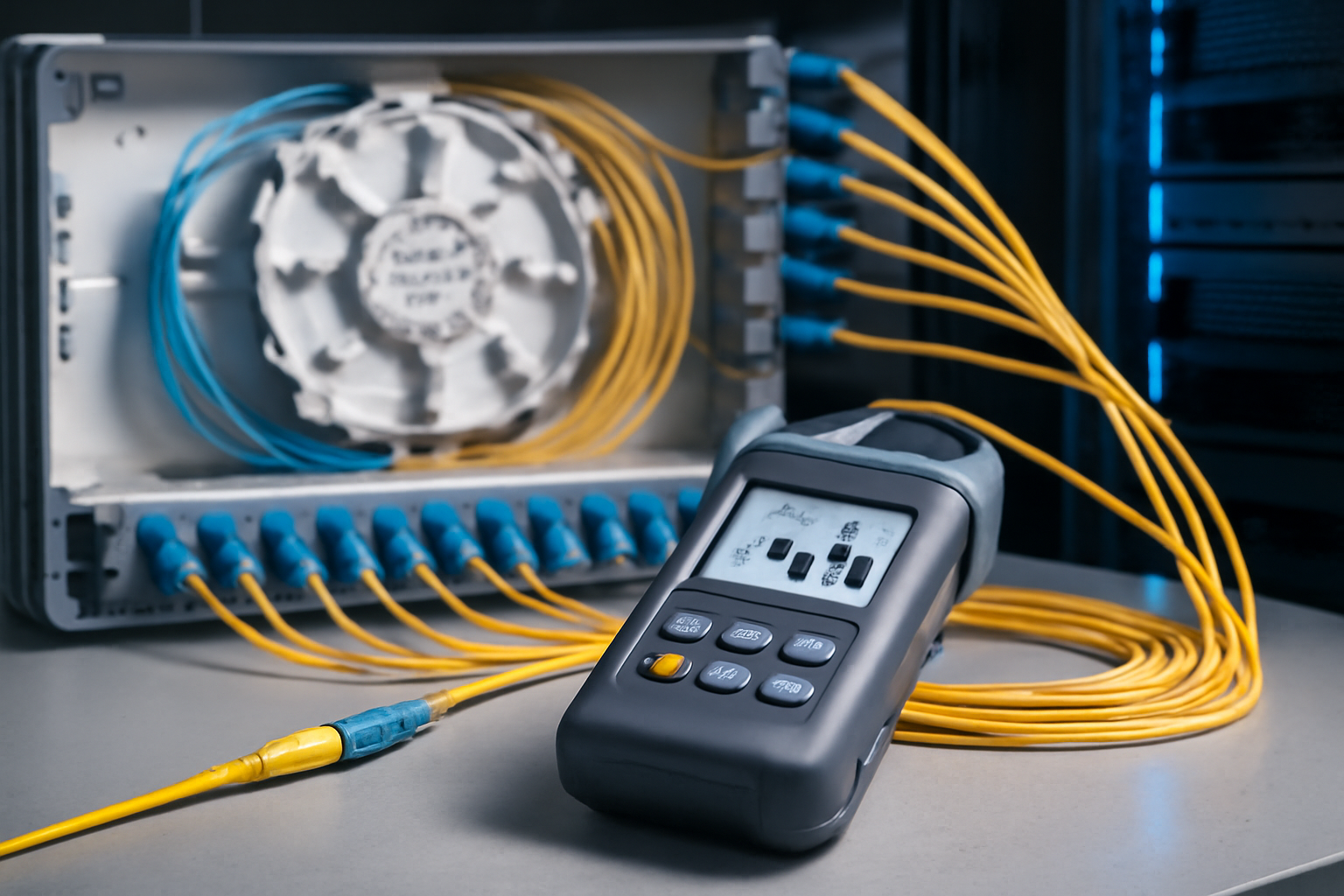
For standards-compliant measurements according to IEC 61300, you need calibrated measurement equipment and clean reference cables. Before each measurement, all connector faces must be cleaned with special cleaning pens – even minor contamination can cause additional attenuation exceeding 1 dB.
The measurement process begins with a reference measurement, during which you zero the measuring device. You then measure the installed line including all splice modules and connectors. The difference from the reference gives the total attenuation, which you compare with your calculated attenuation budget.
Fiber Products Quality Promise: As an official Diamond partner and manufacturer, we produce modular splice systems in Europe. Benefit from Swiss precision and in-house manufacturing.
Calculating Attenuation Budget According to IEC Standards
The attenuation budget of a fibre optic line is calculated from the sum of all individual attenuations. For a typical installation with single-mode fibre at 1310 nm, you calculate 0.35 dB/km fibre attenuation plus losses at all connection points.
| Component | Quantity | Attenuation per element | Total attenuation |
|---|---|---|---|
| Optical fibre 10 km | 1 | 0.35 dB/km | 3.5 dB |
| LC connectors | 4 | 0.3 dB | 1.2 dB |
| Splices | 6 | 0.1 dB | 0.6 dB |
| Margin | – | – | 1.5 dB |
| Total | 6.8 dB |
By using high-quality components such as Diamond E2000 connectors with typical 0.1 dB attenuation, you can significantly optimise your budget. Modern splice modules with precise splice cassettes consistently achieve values below 0.05 dB per splice.
Influence of Wavelength on Optical Fibre Loss
Attenuation in optical fibres is highly wavelength-dependent. Single-mode fibres show a minimum at 1550 nm with approximately 0.2 dB/km, while at 1310 nm typically 0.35 dB/km occurs. You must consider these differences when planning wide-area networks.
- 850 nm (multi-mode): 3.5 dB/km
- 1310 nm (single-mode): 0.35 dB/km
- 1550 nm (single-mode): 0.2 dB/km
- 1625 nm (monitoring): 0.25 dB/km
New hollow-core fibres will reach record values below 0.091 dB/km by 2026, but with higher splice losses of 0.3 to 0.6 dB. For municipal utilities and local network operators, conventional single-mode fibres therefore remain the most economical solution.
Typical Attenuation Values for Various Connector Types
Selecting the right connector type significantly influences your installation’s attenuation budget. While LC and SC connectors are standard in FTTH deployments, E2000 connectors offer additional advantages in industrial environments through their spring-loaded protective shutter and IP65 protection rating.
Ferrule polish quality determines achievable attenuation: PC polish (Physical Contact) typically achieves 0.3 dB, while APC polish (Angled Physical Contact) with 8° angle not only provides lower attenuation but also superior return loss of >60 dB.
- LC/PC: 0.3 dB typical, 0.5 dB maximum
- LC/APC: 0.2 dB typical, 0.5 dB maximum
- E2000/APC: 0.1 dB typical, 0.3 dB maximum
- MPO-12: 0.35 dB typical, 0.75 dB maximum
- MPO-24: 0.5 dB typical, 0.75 dB maximum
Optical Fibre Attenuation in Modular Splice Systems
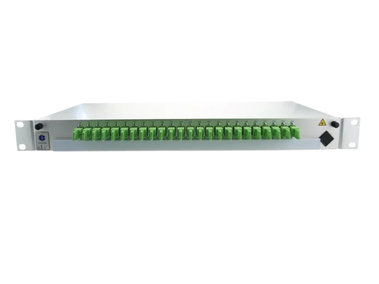
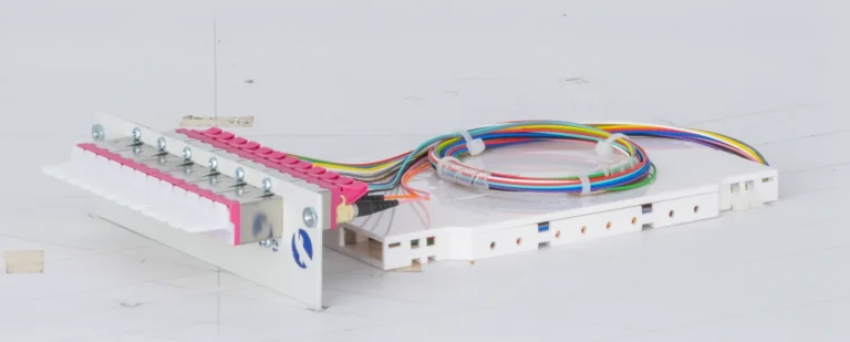
Modern modular splice systems such as SlimConnect and VarioConnect optimise optical fibre attenuation through factory pre-configuration. With up to 96 fibres in 1HE, these systems achieve double packing density whilst simultaneously reducing attenuation values through precise splice cassettes.
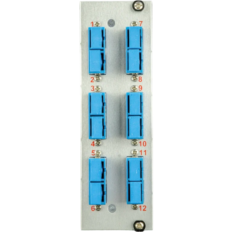
The modular design allows flexible replacement of individual modules without affecting ongoing operations. Each module is individually measured and documented, allowing you to demonstrate IEC 61300 compliance for every single fibre.
Documentation and Reporting According to IEC 61300
Standards-compliant documentation of your attenuation measurements is essential for acceptance protocols and warranty. IEC 61300 requires complete recording of all measured values including measurement equipment used, calibration data and environmental conditions.
- Measurement report with date and time
- Equipment type and serial number
- Calibration status of the instrument (interval per manufacturer and quality plan)
- Measured wavelengths (1310 nm and 1550 nm)
- Individual attenuation of all components
- Total attenuation and comparison with budget
- OTDR curves for troubleshooting
Professional measurement systems such as the FiberXpert 700 generate these protocols automatically and verify compliance with IEC 61300 limits. Integration with documentation systems enables digital handover to the client.
Optimising Optical Fibre Loss in Practice
Minimising optical fibre attenuation begins at the planning stage. By selecting high-quality components with 5 years warranty and precision manufacturing, you can reduce attenuation values well below normative limits. Particularly in critical applications such as data centres, this investment pays for itself through extended transmission distances.
During installation, experienced technicians ensure clean working practices: connector faces are cleaned before each connection, bending radii of at least 30 mm are maintained, and tensile forces are limited below 1000 N. Modern splicing equipment with automatic core alignment consistently achieves attenuation values below 0.05 dB.
Error Sources and Troubleshooting for Elevated Attenuation Values
When your measurements exceed IEC 61300 limits, one of the following causes is usually responsible: contaminated connector faces cause up to 80 percent of all attenuation problems. Micro-cracks from mishandling, faulty splices or macrobending from overly tight routing also lead to increased losses.
- Contamination: additional attenuation >1 dB
- Scratches on ferrule: 0.5 to 2 dB
- Faulty splice: 0.3 to 1 dB
- Macrobending: 0.1 to 5 dB depending on radius
- Incorrect connector pairing (PC/APC): >3 dB
- Ageing/moisture: 0.1 to 0.5 dB/year
Using OTDR, you can precisely locate faulty locations. The characteristic reflection signature shows whether the problem is a connector, splice or bend. With modular systems, you simply replace affected modules.
FAQ: Frequently Asked Questions on Optical Fibre Attenuation According to IEC 61300
Which measurement instruments are approved for IEC 61300-compliant measurements?
IEC 61300-3-4 describes methods for measuring the attenuation of optical components. It approves no particular instrument and defines no accuracy class — figures such as ±0.1 dB / ±0.5 dB and a fixed twelve-month calibration interval do not come from it. Acceptance testing of installed cabling follows ISO/IEC 14763-3, which references IEC 61315 for power meter calibration and IEC 61746-1 and -2 for OTDR calibration. The calibration interval is set by the instrument manufacturer and your own quality plan.
How often must attenuation measurements be performed?
How often attenuation is measured is set by the quality plan for the installation, not by IEC 61300. ISO/IEC 14763-3 states that the quality plan defines which acceptance tests and which sampling level apply; the requirements for it are given in ISO/IEC 14763-2. Testing every fibre is normal acceptance practice and what we recommend, but it is a contractual requirement, not a normative one. Repeat measurements are appropriate after modifications or faults. No IEC standard prescribes annual routine re-measurement.
Which dB limits apply to MPO connectors in data centres?
IEC 61300 sets no limits at all — IEC 61300-1 states that the relevant specification defines the permissible performance limits. For MPO/MTP the component grades come from IEC 61753-1, while the cabling standards ANSI/TIA-568.3 and ISO/IEC 11801 allow a maximum of 0.75 dB per mated connector pair. Quality MPO assemblies do far better: HUBER+SUHNER specifies its MTP-12 and MTP-24 OM4 assemblies (IEC 61753-1 category C) at ≤ 0.35 dB maximum and ≤ 0.1 dB typical. Always calculate the link budget with maximum values, never with typical ones.
How do limits differ between single-mode and multi-mode?
IEC 61300 defines test procedures, not connector limits — a maximum loss per mated pair comes from the cabling standards (ISO/IEC 11801 and EN 50173), and it applies to single-mode and multimode alike. The real difference is in the fibre: multimode at 850 nm attenuates roughly an order of magnitude more per kilometre than single-mode at 1310 nm, where ITU-T G.652 caps the attenuation coefficient at 0.4 dB/km. Take the exact channel limits from the edition of the cabling standard your project cites.
What does the new VDE guideline 0800-730 mean for attenuation measurements?
VDE 0800-730 was published in February 2026 as a VDE guideline on material requirements for FTTH fibre in-building networks, with explicit reference to the EU Gigabit Infrastructure Act (Regulation (EU) 2024/1309). It is guidance, not a binding standard, and it deals with products and their test requirements. It changes nothing about acceptance testing: measure and document every line as before. Note also that a fibre cable is not free of fire load — the jacket still carries a CPR class.
Can I combine different connector types without additional attenuation?
A hybrid adapter between two connector families is the mating point itself, not an extra loss element added on top of it — its loss is the ordinary mated-pair loss of the components involved, and no standard assigns hybrid adapters a blanket surcharge. What is genuinely critical is pairing PC with APC: the 8 degree angle difference prevents physical contact, the loss becomes high and unpredictable, and the end faces can be damaged. Always mate identical polish types and angles.
Conclusion: Precise Attenuation Measurement as Quality Assurance
Exact measurement and compliance with optical fibre attenuation according to IEC 61300 forms the foundation of every professional fibre optic installation. With correct measurement procedures, high-quality components and careful documentation, you ensure long-term performance of your fibre optic network.
Order directly from the shop: fiber-products.de
Request a Quote Today
Free consultation – personalised quote within 24 hours