OTDR Measurement in Fibre Optic Networks: Precise Fault Localisation and Documentation
OTDR Measurement in Fibre Optic Networks: Precise Fault Localisation and Compliant Documentation for FTTH Installations
OTDR measurement enables precise fibre optic attenuation testing and exact optical fibre fault localisation with accuracy of up to 1 metre – essential for compliant acceptance and documentation of FTTH networks per DIN EN 61280-4-2. As optical time-domain reflectometry, OTDR test equipment detects attenuation points, splice losses and fibre breaks via backscatter analysis at 1310 nm and 1550 nm wavelengths. For installers and technicians in German fibre rollout, bidirectional OTDR measurement has become indispensable, as it compensates for directional attenuation differences and ensures complete network documentation for municipal utilities and network operators.
With exponential FTTH deployment in Germany – 8.5 million households already connected – demands on precise test equipment and modular distribution systems are rising. Integration of OTDR measurement protocols into modern splice boxes and distribution systems reduces downtime by up to 40 per cent and significantly shortens fault-finding time.
Fundamentals of OTDR Test Equipment for Fibre Installations
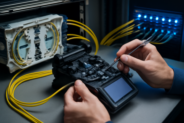
The optical time-domain reflectometer sends short light pulses through the fibre optic cable and analyses returned Rayleigh scattering and Fresnel reflections at connectors and fibre ends. Runtime measurement enables exact localisation of events along the entire route – from the splice box to the endpoint.
- Test wavelengths: 1310 nm for multimode, 1550 nm and 1625 nm for singlemode fibres
- Dynamic range: Modern instruments achieve 45 dB for distances up to 200 km
- Location resolution: Events localisable to < 1 metre accuracy
- Dead zone reduction: Short pulses minimise blind zones to < 3 metres
- Bidirectional measurement: Compensates for backscatter coefficients from different fibre manufacturers
The OTDR curve visualises the complete route profile as attenuation loss across distance. Every deviation from the linear trace signals an event – whether a splice with < 0.1 dB loss or a connector with typical 0.3 to 0.5 dB attenuation.
Bidirectional OTDR Measurement per DIN EN 61280-4-2
Current standard DIN EN 61280-4-2 mandates bidirectional measurements for professional fibre acceptance. This requirement stems from the physical property of differing backscatter coefficients across fibre types and manufacturers.
| Measurement Direction | Attenuation Value | Deviation | Average |
|---|---|---|---|
| A → B | 0.42 dB | +0.07 dB | 0.35 dB |
| B → A | 0.28 dB | -0.07 dB |
The arithmetic mean of both measurement directions eliminates systematic errors and delivers the true attenuation value. Especially in heterogeneous networks with fibres from different manufacturers, this method is essential for compliant documentation.
Typical Fault Patterns and Interpretation
Correct interpretation of OTDR curves requires experience and systematic approach. Each fault pattern shows characteristic features in the attenuation profile.
Macrobending and Mechanical Stress
Excessive bend radius causes localised attenuation increase without reflection. For singlemode fibres, bend radius should be at least 30 mm, during installation even 60 mm. The OTDR curve shows a step-like attenuation rise without reflection spike.
- Attenuation increase: 0.5 to 5 dB depending on bend radius
- Wavelength dependence: Stronger impact at 1550 nm than at 1310 nm
- Localisation: Exact position determination for targeted correction
- Prevention: Use of bend-insensitive G.657.A2 fibres
Contaminated or Damaged Connectors
Contaminated ferrule end-faces are among the most common failure causes in fibre networks. OTDR measurement detects increased attenuation and back-reflection at affected connections. High-quality connector systems with E2000 connectors and integrated shutter considerably reduce this risk.
Fiber Products Quality Commitment: As official Diamond partner and manufacturer, we produce modular splice systems in Europe. Benefit from Swiss precision and 5 years warranty on our systems.
Optimising OTDR Parameters for Different Network Types
Correct parameterisation of the OTDR test instrument determines the reliability of measurement results. Wrong settings lead to misinterpretation or missed faults.
Parameterisation for FTTH Networks (PON)
| Parameter | Recommended Value | Justification |
|---|---|---|
| Wavelength | 1550 nm / 1625 nm | No interference with active operation |
| Pulse Width | 10–30 ns | Balance between resolution and range |
| Measurement Range | 20–40 km | Typical FTTH route lengths |
| Refractive Index | 1.4680 | Standard for G.652.D fibres |
| Averaging Time | 30–60 seconds | Optimal signal-to-noise ratio |
Settings for Data Centre Cabling
In data centres with high packing density and short connections, different parameters are required. The modular splice modules with up to 96 fibres in 1U demand precise short-distance measurements with minimal dead zone.
- Short pulses: 3–5 ns for metre-range resolution
- Precursor distance: Minimum 150 metres to bridge dead zone
- Multimode measurement: 850 nm and 1300 nm for OM3/OM4/OM5
- MPO fanouts: Individual fibre measurement after split required
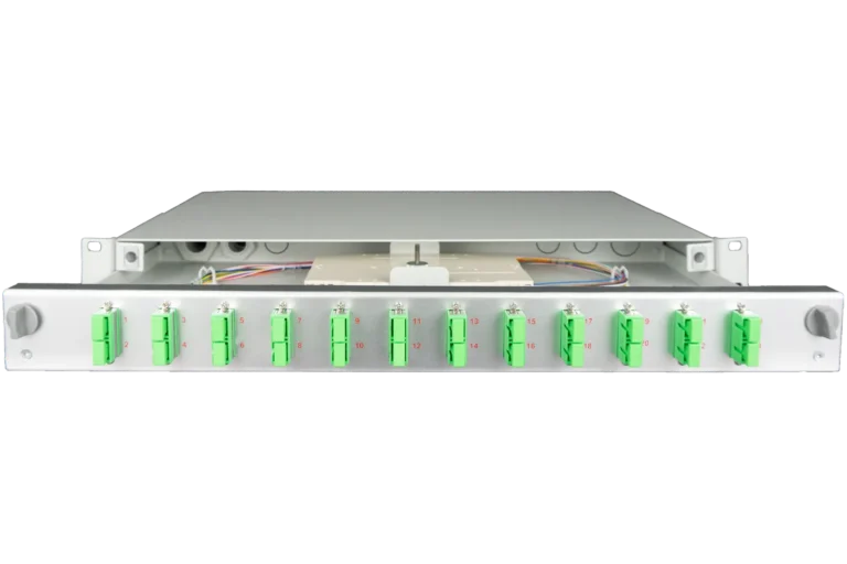
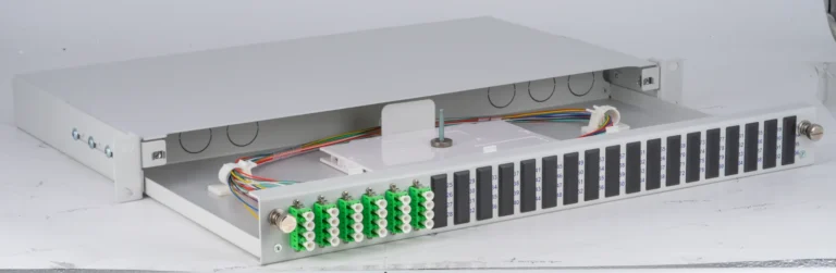
Integration of OTDR Measurement into Modular Distribution Systems
Modern fibre distribution systems must support OTDR measurements optimally. The SlimConnect 1U splice boxes offer ideal conditions for systematic measurement and documentation through their modular design.
Pre-cabling with defined measurement points enables reproducible measurements during installation, acceptance and maintenance. Each fibre is uniquely identifiable and documentable – a decisive advantage when troubleshooting complex networks.
Measurement Concept for Modular Systems
- Reference measurement: Documentation of baseline state after installation
- Periodic monitoring: Quarterly measurements for early degradation detection
- Event-based measurement: During faults or after maintenance work
- Acceptance measurement: Compliant documentation for client
- Trend analysis: Long-term monitoring of critical routes
Fault Diagnosis at Splice Connections
Splice connections should ideally show attenuation of < 0.05 dB. OTDR measurement can indicate both positive and negative splice attenuation – an apparent paradox resulting from different mode field diameters of spliced fibres.
When fusing different fibre types, such as G.652 with G.657, mode field mismatch can occur. Bidirectional measurement averages these effects and delivers the true attenuation value. Modern splicers with active core alignment minimise such losses to < 0.02 dB.
Quality Criteria for Splice Connections
| Quality Level | Attenuation | Back-Reflection | Application |
|---|---|---|---|
| Excellent | < 0.05 dB | < -60 dB | Long-haul networks |
| Good | 0.05–0.10 dB | < -50 dB | FTTH networks |
| Acceptable | 0.10–0.15 dB | < -45 dB | Industrial networks |
| Rework Required | > 0.15 dB | > -45 dB | Not acceptable |
OTDR Documentation for Network Operators and Municipal Utilities
Professional documentation of OTDR measurements is essential for operation, maintenance and expansion of fibre networks. Municipal utilities with owned FTTH networks require complete evidence for subsidies and network management.
Complete OTDR documentation includes bidirectional measurement curves, tabular event lists and graphical route overviews. Each measurement point is recorded with GPS coordinates, timestamp and technician ID. This data forms the foundation for predictive maintenance and capacity planning.
- Route documentation: Complete topology with all distribution points
- Attenuation budget: Evidence of compliance with design specifications
- Event log: Chronological record of all measurements
- Trend analysis: Changes over operating period
- Standards compliance: Evidence per DIN EN 61280-4-2
Troubleshooting with OTDR in Existing Networks
In active network faults, OTDR measurement at 1625 nm or 1650 nm enables fault-finding without service interruption. These wavelengths lie outside transmission bands and do not affect data traffic.
Systematic Approach to Fault-Finding
Structured fault analysis begins with comparison to reference measurement. Deviations exceeding 0.5 dB indicate changes. Localisation occurs through analysis of event positions and attenuation values.
Common field fault causes are mechanical damage from construction work, thermal stress in cable ducts or connector ageing. OTDR measurement not only identifies fault location but also provides clues to the cause through characteristic curve patterns.
Future Trends: Predictive OTDR Analysis
Modern OTDR systems with Raman and Brillouin scattering analysis greatly extend diagnostic capability. Distributed temperature sensing (DTS) detects thermal hotspots along the fibre and enables prediction of imminent failures.
- Temperature monitoring: Detection of overheating in cable routes
- Vibration detection: Early warning of mechanical hazards
- Ageing prediction: Forecast of remaining component lifetime
- AI-assisted analysis: Automatic pattern recognition in measurement curves
- Cloud integration: Centralised monitoring of distributed networks
These technologies reduce unplanned outages and optimise maintenance intervals. For network operators, this means higher availability with reduced operating costs.
Cost-Effectiveness of OTDR Measurement in FTTH Rollout
Investment in high-quality OTDR test equipment pays for itself through shortened installation times and reduced rework. In typical FTTH projects with 1,000 household connections, systematic OTDR documentation saves up to 30 per cent of commissioning time.
Integration into modular distribution systems such as the VarioConnect series with up to 288 fibres enables efficient batch measurements. Pre-configured measurement points and unique fibre identification significantly accelerate the measurement process.
ROI Calculation for OTDR Equipment
| Cost Factor | Without OTDR | With OTDR | Saving |
|---|---|---|---|
| Fault-Finding/Year | 120 hours | 40 hours | 80 hours |
| Rework | 15% | 3% | 12% |
| Downtime | 48 hours | 12 hours | 36 hours |
| Documentation | Manual | Automated | 50% Time Saving |
Best Practices for OTDR Measurement in the Field
Successful OTDR measurements require more than technical knowledge. Proper preparation, clean working practice and systematic documentation are critical for meaningful results.
Checklist for Professional OTDR Measurements
- Cleaning of all connectors with specialist cleaners and microscope verification
- Use of high-quality test cables with LC/APC or E2000/APC connectors
- Precursor distance of at least 150 metres to minimise dead zones
- Equipment calibration per manufacturer guidelines every 12 months
- Bidirectional measurement as standard, not exception
- Immediate documentation with photograph of distribution point
Consistent application of these standards reduces measurement error and ensures comparable results throughout the project lifecycle. Especially in large FTTH rollouts with multiple subcontractors, standardisation is critical to success.
FAQ: Common Questions on OTDR Measurement
Why does my OTDR measurement show negative attenuation at a splice?
Negative attenuation values result from differing backscatter coefficients of spliced fibres. Bidirectional measurement averages this effect and shows the true value. With mode field differences, locally more light can be backscattered than expected.
Which wavelength should I use for FTTH measurements?
For passive networks, 1550 nm is recommended for higher sensitivity to bending. In active PON networks, use 1625 nm or 1650 nm for interference-free in-service measurement. Attenuation is higher at 1550 nm, improving signal clarity in longer routes.
Order direct from our shop: fiber-products.de
Request a Quote
Free consultation – personalised quote within 24 hours