MPO/MTP Connectors: High-Density Fibre Optic Connections for Data Centres
MPO/MTP Connectors: High-Density Fibre Optic Connections for Data Centres
MPO connector and MTP plug enable high-density fibre optic cabling in modern data centres by bundling up to 72 fibres in a single connector – a technology that, paired with MPO patch cables, increases port density by a factor of 12 compared to conventional LC duplex connections. These multi-fibre connector systems conforming to IEC 61754-7 allow data centre operators to terminate up to 288 fibres in just 1U – a packing density that has become indispensable for 400G and 800G network architectures.
The rapid evolution of data centre infrastructure in the DACH region demands a fundamental redesign of the physical cabling layer. While German fibre rollout reaches record numbers with 2.7 million new connections in 2025, data centres face the challenge of designing their backbone cabling for bandwidths beyond the terabit threshold.
Technical Fundamentals: MPO versus MTP Connectors
The MPO connector (Multi-fiber Push-On) is based on a rectangular ferrule made of high-precision polymer, in which the optical fibres are arranged in one or two rows. The most common variants are MPO-12 with 12 fibres in a single row and MPO-24 with 24 fibres in two rows of 12 fibres each. Recent developments include MPO-16 and MPO-32 for specific transceiver architectures.
MTP plugs are an evolution of the MPO standard developed by US Conec. They offer improved mechanical properties such as floating-mounted ferrules for optimal fibre alignment and reduced insertion loss. The retractable guide pins of the MTP enable tool-free gender conversion – a critical advantage during field installation.
- Insertion loss: Elite-grade MPO/MTP achieve < 0.35 dB
- Return loss: Singlemode APC polish achieves > 60 dB
- Mating cycles: Up to 1000 insertions without performance degradation
- Fibre count: 8, 12, 16, 24, 32, 48 or 72 fibres per connector
Polarity Concepts and Fibre Assignment in Practice
Correct polarity is critical for the functionality of high-density fibre optic installations. The TIA-568 standard defines three polarity methods, with Method B becoming the de-facto standard in data centres.
| Polarity method | Cable type | Application | Fibre assignment |
|---|---|---|---|
| Method A | Straight | Backbone cabling | 1→1, 2→2, … 12→12 |
| Method B | Crossed | 40G/100G SR4 standard | 1→12, 2→11, … 12→1 |
| Method C | Flipped | Special applications | 1→2, 2→1, … 11→12 |
The choice of correct polarity depends on the transceiver technology used. Modern 400G-DR4 and 800G-DR8 transceivers use parallel optics with dedicated transmit and receive fibres, requiring precise polarity planning.
Applications: From 40G to 800G Ethernet
The evolution of Ethernet speeds drives adoption of MPO patch cable systems. Each new generation uses the multi-fibre architecture more efficiently.
- 40GBASE-SR4: 4×10G over 8 fibres (4 TX, 4 RX) with MPO-12
- 100GBASE-SR4: 4×25G over 8 fibres with MPO-12
- 200GBASE-SR8: 8×25G over 16 fibres with MPO-16
- 400GBASE-SR8: 8×50G over 16 fibres with MPO-16
- 800GBASE-SR8: 8×100G over 16 fibres with MPO-16
The transition from MPO-12 to MPO-16 for 400G and higher presents challenges for many data centres. The different pin position (central for MPO-12, offset for MPO-16) prevents direct compatibility. Modular splice systems enable flexible migration strategies through interchangeable adapter plates.
Quality Criteria for MPO/MTP Cabling Systems
The quality of an MTP plug system is evident in measurable optical and mechanical parameters. Leading manufacturers classify their products by performance grades.
Optical performance classes per IEC 61755-5: The standard defines four quality grades for maximum insertion loss. Grade B with ≤ 0.25 dB per connection is the premium standard for data centres. Grade C with ≤ 0.50 dB meets the requirements of most enterprise networks.
Ferrule geometry largely determines optical performance. Critical parameters include fibre height (1–3 μm above the ferrule), coplanarity (< 500 nm height variation between fibres) and apex offset (< 50 μm). Precision measurement instruments using interferometer technology validate this micro-geometry.
Fiber Products Quality Promise: As an official Diamond partner and manufacturer, we produce modular splice systems in Europe. Benefit from Swiss precision and 5 years warranty on our systems.
Pre-terminated versus Field Installation
The choice between pre-terminated MPO connector systems and field installation has significant implications for quality and installation time. Pre-terminated solutions are manufactured under cleanroom conditions and individually tested.
- Pre-termination: Guaranteed loss values < 0.35 dB
- Test report: Each individual fibre is documented
- Installation time: 75% reduction compared to field splicing
- Defect rate: Virtually zero through factory quality control
Field termination requires specialised tools and trained personnel. An MPO polishing kit costs between €15,000 and €25,000. Payback occurs only after several hundred connectors per year. Additionally, technicians must complete multi-day training courses to learn proper handling.
Cable Management and Bend Radii
The high fibre density of high-density fibre optic systems requires thoughtful cable management. A single MPO-24 cable replaces twelve LC duplex patch cables but simultaneously reduces flexibility for individual fibre routing.
Critical bend radii per IEC 60794: Modern bend-insensitive fibres (G.657.A2) allow bend radii of 7.5 mm for singlemode and 15 mm for multimode without measurable additional loss. Standard fibres require at least 30 mm bend radius.
| Fibre type | Min. bend radius | Macro bending loss | Standard |
|---|---|---|---|
| OM3/OM4 standard | 30 mm | < 0.1 dB | IEC 60793-2-10 |
| OM5 wideband | 30 mm | < 0.1 dB | IEC 60793-2-10 |
| OS2 G.652.D | 30 mm | < 0.05 dB | ITU-T G.652 |
| OS2 G.657.A2 | 7.5 mm | < 0.1 dB | ITU-T G.657 |
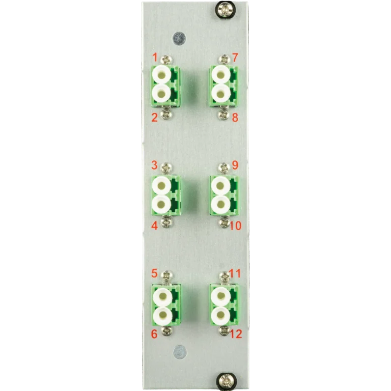
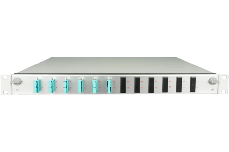
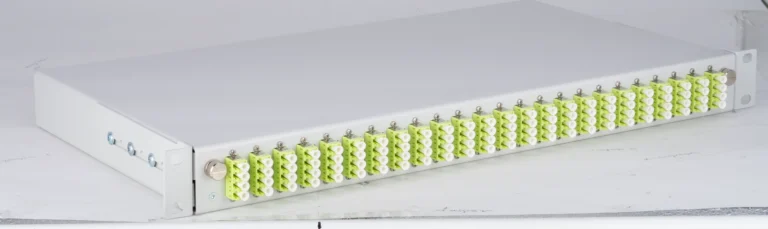
Integration into Modular Splice Systems
Integration of MPO patch cables into structured cabling systems is achieved through splice cassettes and breakout modules. Modern splice modules provide space in 1U for up to 8 MPO cassettes with 12 fibres each – a total of 96 fibres per rack unit.
The advantages of modular systems are particularly evident during technology migrations. A data centre can gradually upgrade from 10G to 40G, 100G or 400G without changing the backbone cabling. Only adapter plates and transceivers need replacement.
- SlimConnect 1U: Up to 96 fibres or 8 MPO ports
- VarioConnect 3U: Up to 288 fibres or 24 MPO ports
- Packing density: 50% higher than competitor systems
- Modularity: Tool-free cassette replacement in under 60 seconds
Cleaning and Maintenance of MPO/MTP Connections
Cleanliness of the end faces is more critical for MTP plug systems than for single-fibre connectors. A single dust particle can affect multiple fibres simultaneously and disable entire transmission channels.
Cleaning procedure per IEC 61300-3-35: The standard defines cleanliness grades for optical connectors. For MPO/MTP, at least Grade B is required, with a maximum of 5 particles > 5 μm in the core zone. Automated inspection systems verify all fibres simultaneously in under 10 seconds.
Specialised MPO cleaning tools use precise fibre guides to clean all 12 or 24 end faces simultaneously. Investment in professional cleaning systems (€2,000–€5,000) pays for itself through avoided network outages.
Standards and Certifications in the DACH Region
Standardisation of high-density fibre optic components follows international and European standards. For the German market, DIN standards are additionally relevant.
- IEC 61754-7: Mechanical interface for MPO connectors
- IEC 61755-3-31: Optical interface for multi-fibre connectors
- EN 50173-1: Generic cabling for data centres
- DIN EN 50173-5: Specific requirements for data centres
- ISO/IEC 11801-5: International standard for data centre cabling
CE marking confirms compliance with European directives. Additionally, many operators demand manufacturer-specific certificates such as Diamond quality certification for the highest precision requirements.
Cost Calculation and Economic Viability
Investment in MPO connector-based infrastructure requires a holistic view of total cost of ownership. Higher initial costs are amortised through reduced installation time and improved scalability.
| Cost item | LC duplex system | MPO-12 system | Saving |
|---|---|---|---|
| Material per 96 fibres | €2,400 | €2,800 | -17% |
| Installation time | 16 hours | 4 hours | 75% |
| Space requirement | 4U | 1U | 75% |
| Total cost 5 years | €8,500 | €5,200 | 39% |
The calculation accounts for material costs, labour (€85/hour for certified technicians), opportunity costs from space requirements and maintenance effort over a 5-year period.
Future Perspectives: 1.6T and Multi-Core Fibres
The next generation of MPO patch cable systems prepares for 1.6 terabit Ethernet. New connector designs with up to 144 fibres are currently being standardised. In parallel, multi-core fibres with multiple cores per fibre are being developed.
Silicon photonics advances the integration of optics and electronics. Co-packaged optics (CPO) will integrate MPO connectors directly into the chip package. This development reduces latency and power consumption by 30–40% respectively.
For data centres in the DACH region, this means: Investment in modular, future-proof splice systems pays dividends long-term. Systems with interchangeable cassettes and flexible fibre assignment enable migration to new standards without complete infrastructure replacement.
Frequently Asked Questions on MPO/MTP Installations
Which polarity do I need for 40G/100G SR4 transceivers?
For standard SR4 transceivers, polarity B (Method B) is required. Fibres 1–4 transmit, fibres 9–12 receive. The middle fibres 5–8 remain unused. This enables bidirectional communication over a single MPO-12 cable.
Can I mix MPO-12 and MPO-24 components?
MPO-24 plugs are mechanically compatible with MPO-12 sockets – only the first 12 fibres are then used. Conversely, an MPO-12 plug does not fit fully into an MPO-24 socket. For maximum flexibility, conversion cassettes are recommended.
How do I recognise the quality of a pre-terminated MPO cable?
High-quality MTP plugs are supplied with an individual test report. This documents insertion loss and return loss for every individual fibre. Additionally, ferrule geometry (fibre height, coplanarity) should be documented. Grade B quality is recommended for data centres.
What influence does connector colour have on performance?
Colour indicates the polish type: green stands for APC (angled physical contact) with 8° angled polish, beige for PC (physical contact) with straight polish. APC provides better return loss (> 60 dB) and is preferred for singlemode applications. Multimode typically uses PC polish.
How many mating cycles can an MPO/MTP connector withstand?
Quality connectors achieve 500–1000 mating cycles without measurable degradation. The prerequisite is careful cleaning before each mating operation. Contaminated connectors can suffer permanent damage after just a few cycles.
Is investment in MPO test equipment worthwhile?
For data centres with more than 500 MPO connections, in-house test equipment is economically justified. An MPO test set with OTDR and power meter costs €15,000–€25,000.
Order directly from the shop: fiber-products.de
Request a quote today
Free consultation – personalised quote within 24 hours