Fiber optic splice modules installation explained: How professional commissioning works
Splice modules Fiber optic installation is the heart of any professional fiber optic infrastructure. They protect and organize the sensitive connection points between optical fibres and play a decisive role in the quality, reliability and ease of maintenance of the entire network. While connectors can be quickly disconnected and reconnected, splice connections create permanent, low-loss transitions between different fiber optic cables.
The quality of a fiber optic installation stands and falls with its weakest links – the connections between the fibers. While a poorly executed splice can affect the entire signal, high-quality splice modules enable fiber optic installation connections with attenuation losses of less than 0.1 dB. These minimal losses add up to significant differences in range and signal quality across an entire network.
Modern splice modules have evolved from simple protective housings to complex organizational systems that support various splicing techniques and create maintenance-friendly installations. They have become indispensable for fiber optic solutions for data centers.
Basics of fiber optic splicing technology
Splicing refers to the permanent connection of two optical fibers to form a continuous optical connection. In contrast to connectors, which are detachable, splice connections create permanent transitions with minimal optical losses.
Why splice modules fiber optic installation is necessary
Fibre optic cables are manufactured in standardized lengths – typically 2-4 km per cable drum. For longer distances or complex network structures, several cable sections must be connected together. Splice connections enable these transitions with minimal signal loss.
In addition, network topologies often require branches or transitions between different cable types. For example, a main cable with 144 fibers must be divided into several smaller distribution cables with 12 or 24 fibers each. Fiber optic solutions for municipal utilities use such structures for municipal fiber optic expansion.
The alternative – exclusively pre-assembled cables with connectors – would be uneconomical for larger installations and would lead to unacceptably high overall attenuation. Each connector causes at least 0.3-0.5 dB loss, while fusion splices achieve less than 0.1 dB.
Physical principles of splicing
During splicing, the ends of two optical fibers are precisely aligned and permanently joined together. The quality of this connection depends on the accuracy of the alignment, the cleanliness of the fiber surfaces and the joining process used.
Glass fibers have a core diameter of only 8-9 micrometers (singlemode) or 50-62.5 micrometers (multimode). Even the smallest offsets, angular deviations or surface impurities cause measurable attenuation losses or reflections.
The two main methods – fusion splicing and mechanical splicing – use different approaches to fiber splicing, but both achieve durable, reliable transitions when used correctly.
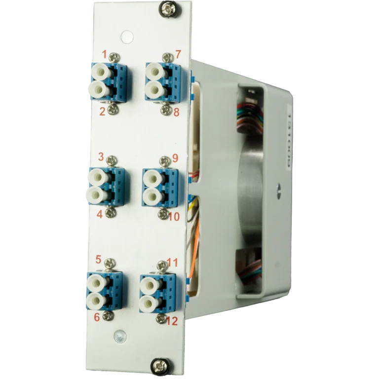
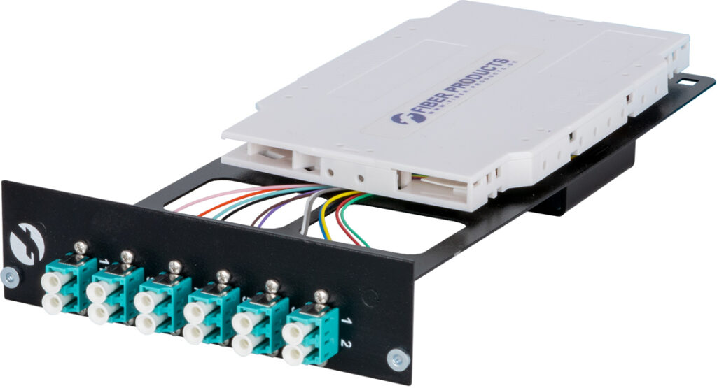
Structure and components of splice modules
Splice modules are specialized housings that protect splice connections from mechanical and environmental influences and at the same time enable systematic organization of the fiber connections.
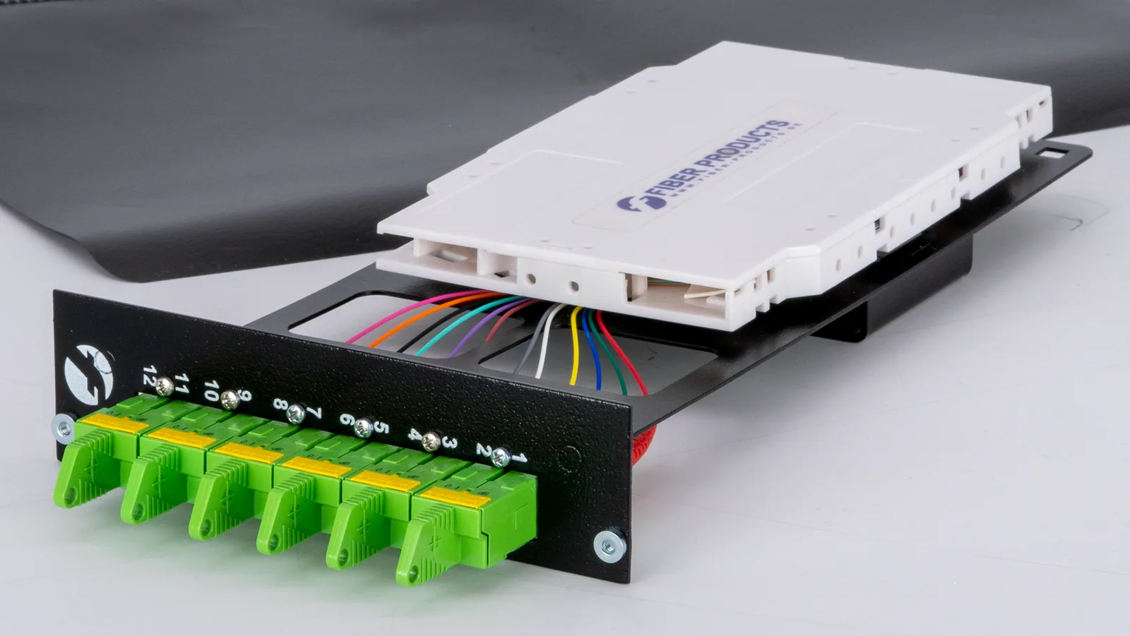
Basic structure of a splice cassette
A typical splice cassette for fiber optic installation splice modules consists of a robust housing, splice holders, fiber guides and cable strain reliefs. The housing protects the sensitive splice points from moisture, dust and mechanical stress.
Housing construction:
- Robust plastic or metal design
- Seals against moisture and dust
- Transparent or removable covers
- Stackable or side-by-side mountable design
Splice holder:
- Holder for various splice protection sleeves
- Secure fixation without damage
- Clear arrangement for easy maintenance
- Compatibility with standard protection products
Fiber routing and cable management
Professional splice modules Fiber optic installation provides systematic fiber routing, which is crucial both during installation and for subsequent maintenance work.
Cable entries:
- Strain relief for incoming cables
- Sealing against environmental influences
- Flexible positioning depending on the installation situation
- Cable diameter adjustments
Fiber organization:
- Defined paths for individual fibers
- Service loops for repair reserves
- Separation between different cable directions
- Bending radius control to protect the fibers
Fiber optic solutions for installers benefit in particular from systematic fiber organization.
Fusion vs. mechanical splicing
The two main methods of fiber optic connection differ fundamentally in terms of technology, application and results.
Fusion splicing – the gold standard
In fusion splicing, the glass fiber ends are fused together under controlled conditions. An electric arc heats the fiber ends to around 2000°C, which melts the glass and creates a molecular bond.
Process steps for splice modules fiber optic installation:
- Precise cleaving (cutting) of the fiber ends
- Cleaning and positioning in the splicer
- Automatic alignment of the fiber cores
- Fusion by controlled arc
- Testing the splice quality
- Protection by splice sleeve
Advantages of fusion splicing:
- Lowest attenuation losses (< 0.1 dB)
- Highest mechanical strength
- Permanent, ageing-resistant connection
- Lowest reflection losses (> 60 dB return loss)
- Reproducible quality with automated devices
Mechanical splicing – the practical alternative for splice modules Fiber optic installation
Mechanical splice connectors use precision-engineered guides and index gel to hold two fiber ends in exact alignment. The connection is made without the application of heat.
Functional principle:
- V-shaped precision guides for both fibers
- Index matching gel between the fiber end faces
- Mechanical fixation through clamping
- Integrated splice protection sleeve
Advantages of mechanical splices:
- No power supply required
- Quick installation (30-60 seconds)
- Lower acquisition costs
- Easy handling even for unskilled workers
- Detachable connections for special types
Fiber optic solutions for industry use both processes depending on the specific requirements.
Areas of application and selection criteria
The choice between fusion and mechanical splicing for fiber optic splice module installation depends on project requirements, budget and available infrastructure.
Fusion splicing preferred for:
- Main distributors and critical connections
- Long transmission distances with attenuation budget restrictions
- Permanent installations without planned changes
- Availability of power supply and trained personnel
Mechanical splicing suitable for:
- Temporary or emergency repairs
- Installations without power supply
- Frequent reconfigurations
- Limited budgets or time pressure
- Simple point-to-point connections
Fiber optic solutions for network operators usually require a combination of both methods.
Installation and best practices
Professional fiber optic splice module installation requires a systematic approach and adherence to best practices.
Preparation and planning
Successful splice installations start with careful preparation. All required materials, tools and documentation should be fully available before starting work.
Planning steps:
- Create fiber plan with all connections
- Determine cassette type and number
- Select splicing method according to requirements
- Provide tools and consumables
- Set up a workplace with adequate lighting
Step-by-step splice box fiber optic installation
1. cassette installation: Position the splice cassette according to the fiber plan, ensure mechanical fastening and prepare the cable entries according to the cabling.
2. cable preparation: remove cable sheath (typically 1-3 meters), split buffer fibers or loose tubes, cut individual fibers according to length planning and install strain relief at cable entries.
3. organize the fibre guide: Lay service loops at a defined length, sort fibers according to the connection plan, observe bending radius limits and attach intermediate fixings to prevent slippage.
4. make splice connections: Prepare fiber ends cleave or mechanically, perform splice according to selected procedure, attenuation measurement for quality control and install splice protection sleeve.
Fiber optic solutions for system houses require special documentation standards.
Quality control and measurements
Professional splice modules Fiber optic installation requires systematic quality control of all splice connections.
Optical measurements
- Attenuation measurement with calibrated power meters
- OTDR measurements for reflection analysis
- Continuity test with visual fault locators
- Polarization analysis for high-quality installations
Mechanical tests
- Tensile strength of the splice connections
- Bending radius control in cassettes
- Cassette closure and tightness
- Labeling for completeness and legibility
Maintenance and fault diagnosis
Splice modules are generally low-maintenance, but require occasional inspections and professional fault diagnosis in the event of problems.
Preventive maintenance
Regular inspections can detect problems at an early stage and prevent breakdowns.
Maintenance intervals:
- Visual inspection: every six months
- Accessibility test: annually
- Optical control measurements: if required
- Cassette cleaning: when dirty
Typical problems and diagnosis of splice modules fiber optic installation
Increased damping:
- Check splice quality with OTDR
- Check bending radius in service loops
- Moisture or dirt in the cassette
- Mechanical load on the splice
Intermittent disorders:
- Tighten loose splice holder
- Temperature effects on mechanical splices
- Microbending due to tight fiber guidance
- Vibration load on the installation
Fiber optic solutions for educational institutions require particularly reliable systems.
Choosing the right splice modules Fiber optic installation
The selection of suitable modules for splice modules fiber optic installation depends on project requirements, environmental conditions and budget.
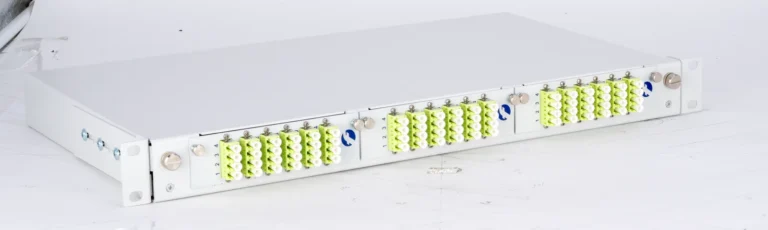
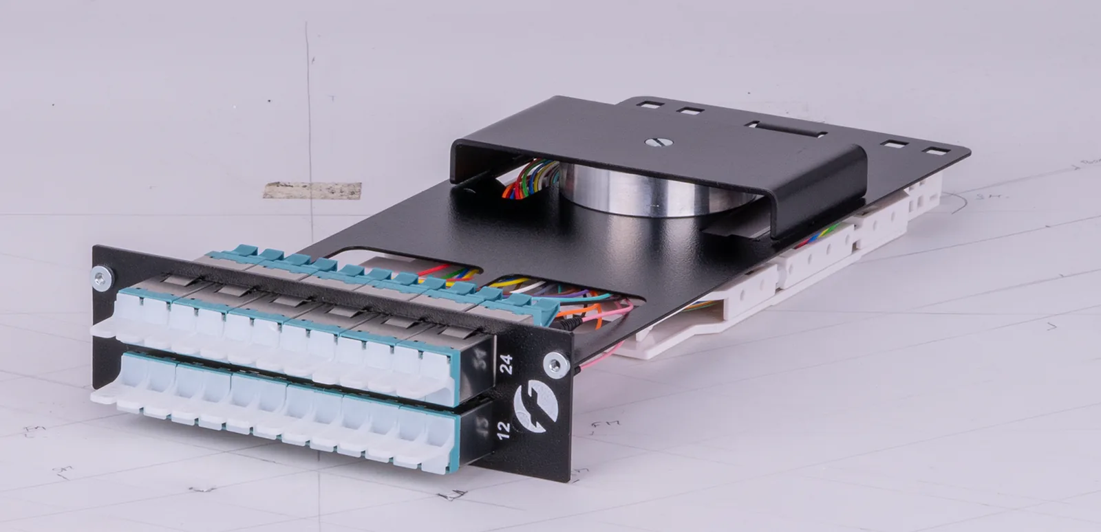
Capacity and dimensioning
Number of fibers per cassette:
- 6-12 Splices: Compact applications
- 12-24 splices: standard installations
- 24-48 Splices: High density systems
- 48+ splices: Central distributor
The capacity should provide 20-50% reserves for future expansions.
Environmental requirements
Indoor installations:
- Standard cassettes with basic seal
- Temperature range 0°C to +60°C
- Relative humidity up to 90%
Outdoor installations:
- IP65/IP67 protection class required
- Extended temperature range (-40°C to +70°C)
- UV resistance and weather protection
- Pressure equalization against condensation
Fiberglass modules for offshore wind power place the highest demands on the installation.
Future developments and trends
Splice Modules Fiber Optic Installation continues to evolve and integrate new technologies for improved performance and ease of use.
Automation and intelligence
Smart Splice cassettes:
- Integrated sensors for environmental monitoring
- RFID tags for automatic documentation
- LED lighting for improved visibility
- Electrical contacts for cassette recognition
Automated quality control:
- Integrated optical measurements
- Continuous attenuation monitoring
- Alarm in the event of quality deterioration
- Predictive maintenance based on measurement data
Higher densities and new technologies
Ultra-high-density cassettes:
- Up to 144 splices per standard cassette
- Miniaturized splice holders and guides
- Ribbon fiber compatibility
- Automated fiber organization
Smart City fiber optic projects are driving these developments forward.
Sustainability and environmental aspects
Environmentally friendly materials:
- Recyclable cassette housing
- Biodegradable splice protection materials
- Reduced packaging and transport optimization
- Durable designs for 25+ years of operation
Circular economy:
- Take-back programs for old cassettes
- Refurbishment and reuse
- Modular design for parts replacement
- Repairability instead of a throwaway mentality
Conclusion: Splice modules as a basis for quality
Splice modules fibre optic installation is far more than just the protection of fibre connections – it forms the organizational and qualitative basis of professional fibre optic networks. The correct selection, professional splice modules fiber optic installation and systematic maintenance of splice modules are decisive for the performance, reliability and cost-effectiveness of the entire fiber optic infrastructure.
The most important success factors
- Quality before price – high-quality modules pay off in the long term thanks to lower maintenance costs
- Demand-oriented dimensioning – planning sufficient capacities with expansion reserves
- Systematic installation – professional fiber organization and documentation right from the start
- Regular maintenance – preventive inspections prevent costly breakdowns
- Future-proof – modular, expandable systems for growing requirements
Application recommendations
- Critical connections: Fusion splicing in high-quality cassettes
- Standard installations: Modular cassette systems for flexibility
- Repairs/emergencies: Mechanical splices for quick solutions
- Outdoor use: IP65+ cassettes with environmental protection
- Growing networks: Scalable frame systems with interchangeable cassettes
Investing in high-quality splice modules and professional installation pays off over the entire operating time through lower attenuation losses, higher availability and easier maintenance. Splice modules are not the place for cost savings – this is where the quality of the entire network is crucial.
Professional splicing technology for lasting quality
Successful fiber optic networks are based on professional splice connections in high-quality protection modules. Sophisticated fiber organization, systematic documentation and maintenance-friendly design are crucial for long-term success.
At Fiber Products, we develop splice modules to meet the highest quality standards. Our modular cassette systems combine proven splicing technology with innovative cable management features. From compact splice boxes to high-capacity ODF integrations, all modules are designed for optimal fiber organization and easy maintenance.
With a 5-year guarantee and Europe-wide production, we offer the reliability that professional fiber optic networks need. Discover our complete product range or visit our online store.
Contact us – together we will develop the optimum splicing solution for your network. For optimum splice modules Fiber optic installation Contact us for individual advice or find out about other specialist topics in our fiber optic knowledge blog.
4. MIDJOURNEY PROMPTS FOR VISUALS
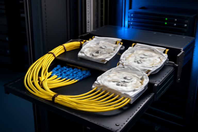
- Hero image:
Professional fiber optic splice module installation in technical environment, technician working with precision tools, corporate blue and white lighting, clean industrial setting, high-tech atmosphere --ar 16:9 --style professional - Splicing process comparison:
Split screen showing fusion splicing vs mechanical splicing techniques, detailed technical processes, blue and white corporate colors, professional equipment, educational style --ar 16:9 --style technical - Cassette structure:
Detailed cutaway view of splice module showing internal components, fiber management system, technical illustration style, precise engineering details, corporate blue accents --ar 16:9 --style technical - Installation process:
Step-by-step splice module installation process, professional technician hands, organized fiber management, clean workspace, documentary photography style --ar 16:9 --style documentary - Quality control:
OTDR measurement equipment testing splice connections, professional testing environment, digital displays showing low loss values, high-tech professional atmosphere --ar 16:9 --style professional