Smart Metering Fibre Optic – Fibre as Backbone for Meter Infrastructure
Smart Metering Fibre Optic – Fibre as Backbone for Meter Infrastructure
Smart Metering fibre optic, energy supplier optical fibre networks and Advanced Metering Infrastructure (AMI) form the technical backbone for digital transformation in the energy sector – only comprehensive optical fibre infrastructure enables intelligent metering systems to be reliably connected and real-time data transmitted securely. The convergence of energy supply and telecommunications creates new demands on passive fibre optic infrastructure. Municipal utilities and meter operators require high-availability connections with latencies below 20 ms and bandwidth of at least 100 Mbit/s per concentrator.
Technical Requirements for Smart Metering Fibre Optic Infrastructure
Connecting intelligent metering systems via fibre optic requires carefully planned network architecture. Every Smart Meter Gateway administrator needs redundant fibre paths to secure critical measurement data. When planning, energy suppliers must consider IEC 61850-9-2 for measurement value transmission and IEC 62351 for data security.
- Primary path via dedicated singlemode fibre (OS2) with 9/125 μm core diameter
- Secondary path as backup connection via separate route
- Attenuation budget of maximum 0.35 dB/km at 1310 nm wavelength
- Minimum 12 fibres per distribution point for future expansion
- Fused connections with < 0.1 dB insertion loss
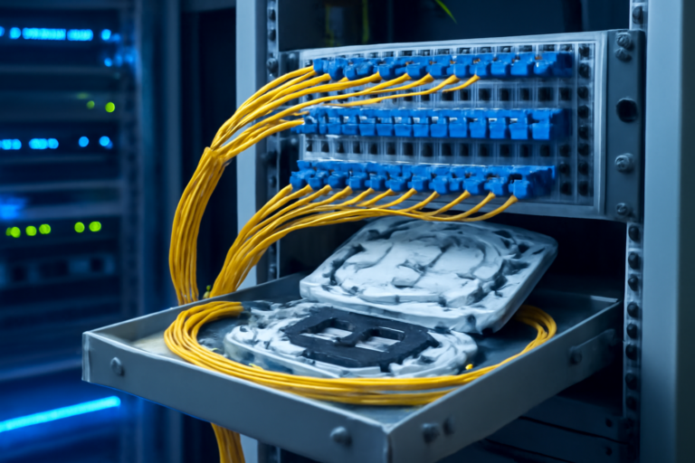
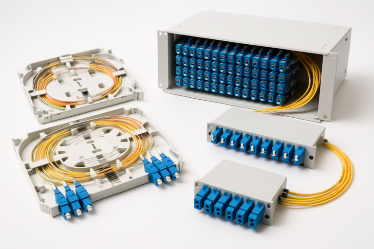
The modular splice technology enables flexible adjustments as connection numbers grow. Modern splice modules achieve a packing density of up to 96 fibres in 1HE, significantly reducing infrastructure costs.
AMI Fibre Optic Architecture for Meter Operators
Advanced Metering Infrastructure (AMI) via optical fibre requires hierarchical network structure. Fibre optic connections typically operate across three levels: from central data centre through regional distribution points to local concentrators. Each level has specific technical requirements for fibre infrastructure.
| Network Level | Fibre Type | Connector | Attenuation Budget |
|---|---|---|---|
| Backbone (Data Centre) | OS2 Singlemode | LC/APC Duplex | < 10 dB |
| Distribution Level (Regional) | OS2 Singlemode | SC/APC or E2000 | < 7 dB |
| Access Network (Local) | OS2 or OM4 | LC/PC or SC/PC | < 5 dB |
Energy supplier optical fibre networks particularly benefit from E2000 connector technology with integrated protective shutter. This ensures consistent transmission quality even in harsh environments with return loss values of > 60 dB.
Integration into Existing Municipal Utility Infrastructure
Retrofitting Smart Metering fibre optic into existing supply networks presents municipal utilities with special challenges. Many energy suppliers already use conduit systems for power distribution, which are suitable for parallel installation of fibre optic cables. Shared use reduces civil works costs by up to 70 percent.
- Microcable installation in existing protective ducts (diameter 10–14 mm)
- Blowing fibre bundles with up to 288 fibres per cable
- Using existing chambers for splice closures and distribution points
- Integration into substations with IP65-rated distribution equipment
- Connection to municipal fibre networks via defined handover points
Fiber Products Quality Commitment: As official Diamond Partner and manufacturer, we produce modular splice systems in Europe. Benefit from Swiss precision and 5-year warranty on our systems.
Redundancy Concepts for Critical Measurement Data Transmission
AMI fibre optic networks are critical infrastructure and require maximum availability. The German Federal Network Agency mandates at least 99.95 percent availability for Smart Grid applications. This corresponds to a maximum downtime of 4.4 hours per year.
Energy supplier optical fibre systems must therefore be fully redundantly designed. Modern splice modules support switchover between primary and secondary fibre within < 50 ms. Physical separation of fibre routes prevents simultaneous failures from excavation damage or other mechanical impact.
| Redundancy Level | Technical Implementation | Switchover Time | Additional Cost |
|---|---|---|---|
| Fibre Level | Dual fibre routing | < 50 ms | + 30% |
| Route Level | Separate cable paths | < 100 ms | + 60% |
| System Level | Parallel infrastructure | < 200 ms | + 100% |
Splice Technology for Decentralised Gateway Structures
Distribution of Smart Meter Gateways across decentralised sites requires flexible splice solutions. Each concentration point needs its own splice box with sufficient reserve capacity. When sizing, meter operators should plan for growth of 30 percent within the next five years.
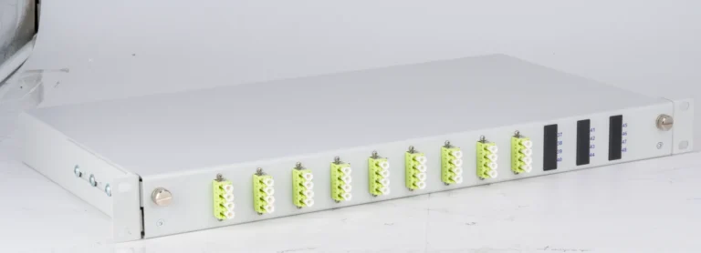
- Splice boxes with 24 to 96 fibre terminations depending on service area
- Pre-terminated pigtails for rapid installation
- Colour coding per DIN VDE 0888-2 for clear identification
- Bend radius management with R > 30 mm for macrobends
- Documentation of all connections in centralised network management
The modular design of SlimConnect systems enables retrofitting without operational interruption. Individual modules can be swapped and expanded during live operation.
Standards-Compliant Installation per VDE and FTTH Standards
Smart Metering fibre optic is subject to strict installation requirements. VDE-AR-N 4140 defines technical connection conditions for integration into low-voltage networks. Additionally, FTTH Council guidelines apply to passive infrastructure.
During installation, energy suppliers must pay particular attention to compliance with optical budgets. Each connector typically adds 0.3 dB attenuation, while splices with < 0.1 dB are negligible. Total attenuation between gateway and data concentrator must not exceed 15 dB.
Economic Viability of Fibre Optic for AMI Applications
Investment in optical fibre infrastructure for Smart Metering pays for itself long-term through lower operating costs. Compared to copper-based or radio solutions, fibre optic offers decisive economic advantages for meter operators.
- No amplifiers required on distances up to 40 km
- Energy consumption 85 percent lower than DSL modems
- Maintenance intervals of 10 years instead of annual testing
- Bandwidth reserves for future services without reinstallation
- Fibre lifespan of at least 25 years
Return on investment for AMI fibre optic typically ranges from 6 to 8 years, depending on connection density and saved meter reading costs.
Cybersecurity in Smart Metering Fibre Optic Networks
Transmission of sensitive consumption data requires highest security standards. Fibre optic offers inherent advantages over other transmission media: eavesdropping attempts are immediately detectable through attenuation changes. BSI TR-03109 defines additional encryption requirements for Smart Meter Gateways.
Energy suppliers must plan separate VLANs for different data streams when designing networks. Critical control commands run separately from regular measurement data. Physical segmentation through dedicated fibres further increases security.
Migration Strategy from Copper to Fibre Optic
Many meter operators still use copper-based connections for remote meter reading. Migration to Smart Metering fibre optic ideally occurs in phases. Critical large consumers and feeders are switched first, followed by commercial customers and finally residential consumers.
| Migration Phase | Customer Group | Priority | Timeframe |
|---|---|---|---|
| Phase 1 | RLM customers > 100,000 kWh/a | Critical | 6 months |
| Phase 2 | Feeders > 30 kW | High | 12 months |
| Phase 3 | Commercial customers | Medium | 18 months |
| Phase 4 | Residential customers | Standard | 36 months |
Scalable Distribution Architecture for Growing Connection Numbers
Introduction of dynamic electricity tariffs and integration of renewable energy sources drive demand for intelligent metering systems. Energy supplier optical fibre networks must be planned for scalability from the outset. Modular splice systems with hot-swap functionality enable expansion without interruption.
- Initial deployment with 40 percent capacity utilisation of splice modules
- Phased expansion at 70 percent utilisation
- Reserve fibres for express connections between distribution points
- Preparation for future 400G Ethernet connections
- Documentation of available capacity in GIS system
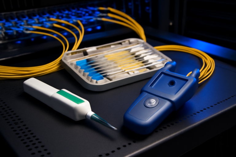
Quality Assurance and Acceptance Measurements
Every AMI fibre optic installation must be documented metrologically. DIN EN 61300-3-35 defines test procedures for connectors, while IEC 61280-4-1 governs OTDR measurements. Meter operators should document the following parameters:
Attenuation of each fibre is measured bidirectionally and must not exceed 0.4 dB/km at 1310 nm. Splice points are rated at maximum 0.15 dB, while connectors must not exceed 0.5 dB. Chromatic dispersion in modern singlemode fibres is below 3.5 ps/(nm·km).
Frequently Asked Questions about Smart Metering Fibre Optic
What bandwidth does a Smart Meter Gateway require via fibre optic?
A single gateway requires 2–5 Mbit/s symmetrical bandwidth during normal operation. During firmware updates, up to 50 Mbit/s may be temporarily required. Per data concentrator with 100 gateways, at least 500 Mbit/s should be planned.
How do APC and PC connectors differ in AMI applications?
APC connectors (Angled Physical Contact) with 8° angled finish provide return loss of > 60 dB and suit critical transmission routes. PC connectors achieve only 45 dB and should only be used in non-critical areas.
Which splice modules are suitable for decentralised gateway installations?
Compact 1HE splice modules with 24 to 48 fibre terminations are recommended for decentralised sites. These provide sufficient capacity for typical district solutions and fit space-efficiently in existing technical rooms.
How long does migration from copper to fibre take?
Complete migration of a supply area with 10,000 metering points typically takes 18 to 24 months. Critical large consumers can be switched within 3 months.
Which standards apply to Smart Metering via optical fibre?
Key standards are VDE-AR-N 4140 for technical connection conditions, BSI TR-03109 for IT security and FNN specifications for gateway administration. Fibre optic installation follows DIN VDE 0888.
Can existing fibre optic infrastructure be shared?
Yes, existing municipal utility fibre networks can be used multiple times through wavelength division multiplexing (CWDM/DWDM). Up to 40 channels per fibre are possible with DWDM, significantly reducing investment costs.
Request a Quote
Have questions about our fibre optic solutions? Our expert team is happy to advise you – free and without obligation.