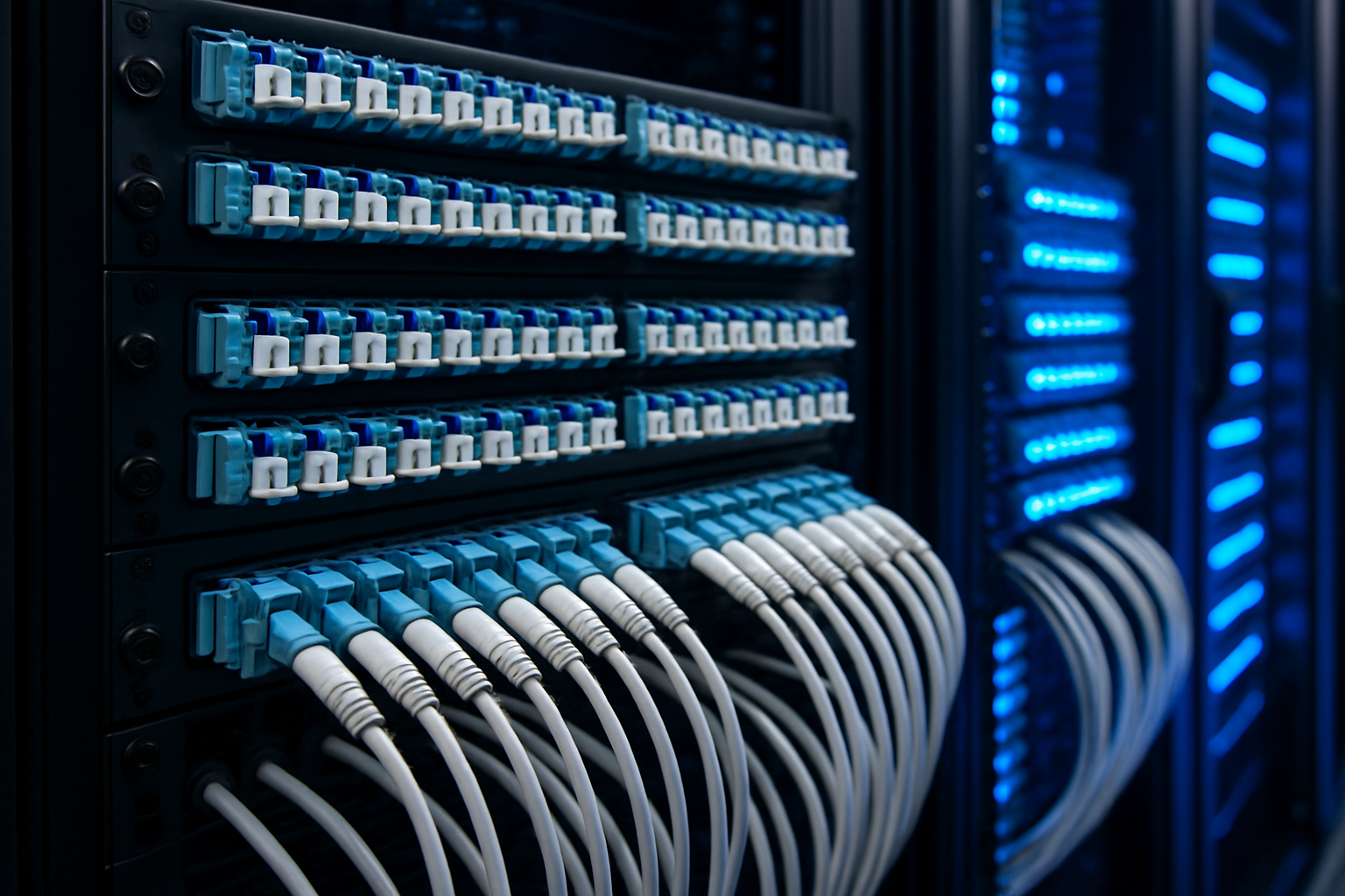
High Density Fibre Optic Systems: Maximum Port Density for Modern Data Centres

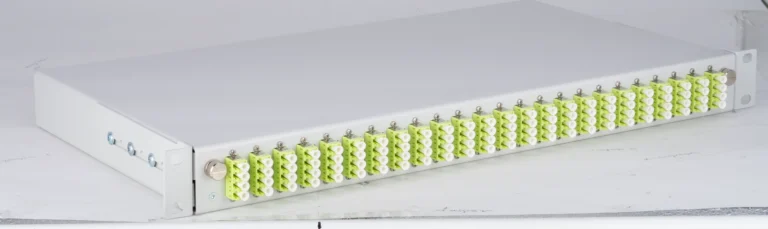
The explosive growth of data volumes in modern high-density fibre optic data centres is driving the development of increasingly compact fibre optic solutions. High-density fibre optic systems with up to 288 fibres in 3U or 72 fibres in 1U represent efficient solutions for maximum port density with minimal rack footprint. This technology is enabled by innovative connector designs, optimised cable management and intelligent modular construction.
Where traditional fibre optic distribution quickly reaches spatial limits, high-density fibre optic data centre solutions such as the modular VarioConnect system with 288 fibres in 3U or SlimConnect with 96 fibres in 1U create space for the growing demands of 400G/800G transmission.
The challenge lies in port density and maintainability balance — a balance that modern modular systems successfully achieve through well-designed 7U module construction. For data centre planners and network architects, these technologies have become essential to manage increasing space requirements while meeting growing performance demands.
Technical foundations of high-density technology
High-density fibre optic data centre technology is based on miniaturising all involved components without compromising optical performance. The key lies in using high-precision micro-connectors such as MTP/MPO, which combine up to 24 fibres in a single connector. Through parallel arrangement and multi-stage cassette systems, extreme port densities of 864 fibres per 1U unit can be achieved.
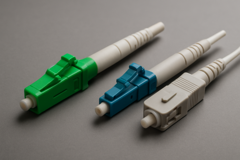
Connector technology for maximum density
Connector technology uses precision-manufactured ferrules with sub-micron tolerances to ensure excellent optical properties despite compact construction. MTP-24 connectors achieve typical insertion losses of 0.35 dB and return losses exceeding 55 dB, making them suitable even for the most demanding high-density fibre optic data centre applications.
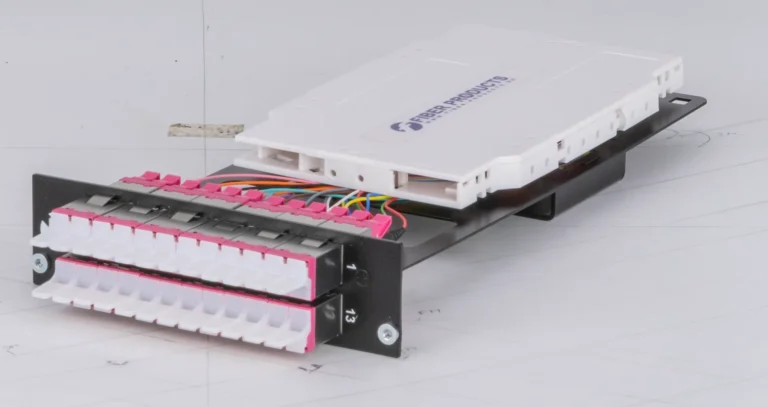
Parallel fibre routing requires precise mechanical alignment of all 24 fibres, which is achieved through special guide elements and adjustment procedures. Splice modules with integrated MTP cassette technology support this high-precision installation.
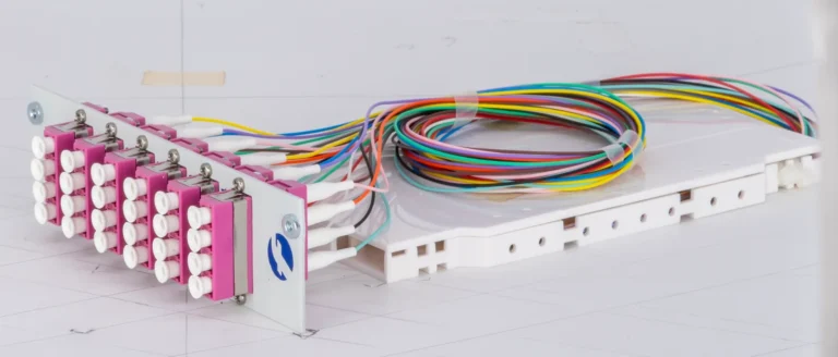
Cassette systems and modular organisation
Cassette systems enable structured organisation of high fibre counts: each cassette typically houses 144 fibres and can be inserted into high-density enclosures without tools. This modularity supports both staged installation and flexible reconfiguration as requirements change.
Cassettes contain integrated splice holders and fibre guides that maintain correct bend radii even at extreme packing densities. 7U DIN rail boxes offer additional flexibility for decentralised applications.
Design principles and system architecture
The system architecture of high-density fibre optic data centre solutions follows hierarchical principles that enable maximum flexibility with compact construction. The VarioConnect 3U system accommodates twelve 7U splice modules, achieving up to 288 fibres, while the compact VarioConnect 1U system houses three 7U front modules for up to 72 fibres.
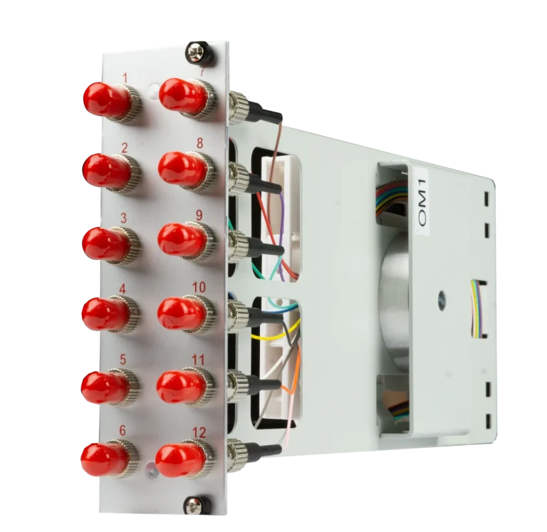
Front modules and interfaces
Front modules with MTP-24 adapters form the interface to active network equipment: each module features six MTP ports connected via internal fibre routing to rear-side cassettes. This separation of front and rear enables independent installation of patch cables and backbone cabling without mutual interference.
Tool-free module technology supports rapid reconfiguration during operation — a decisive advantage for high-density fibre optic data centre environments with high availability requirements.
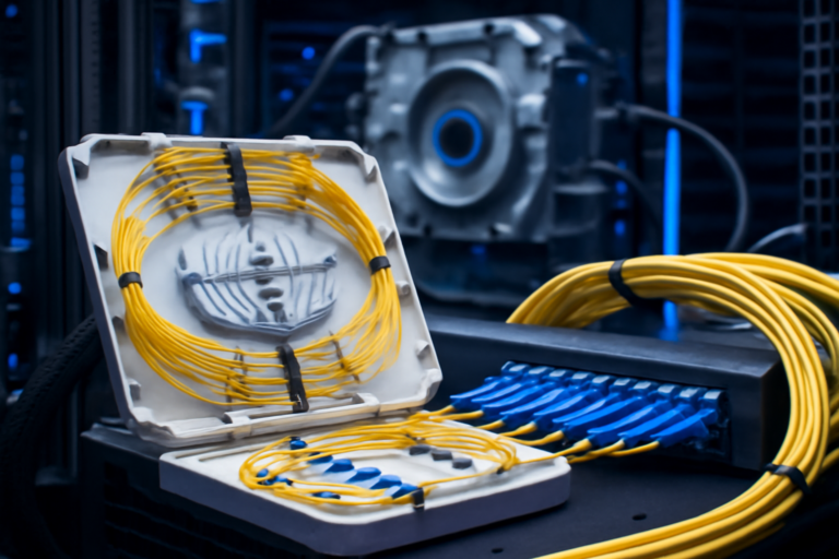
Internal fibre routing and cable management
Internal fibre routing uses precisely dimensioned guide channels that route each of 864 optical fibres individually: multi-layer guide levels prevent crossings and ensure defined bend radii. Special guide rings with diameters of 25–30 mm are precisely matched to the fibre types used.
Cable management systems must be particularly sophisticated in high-density fibre optic data centre applications: each of 864 fibres must remain individually accessible while optimally utilising the limited space. Multi-stage routing systems with various guide levels prevent fibre crossings and enable systematic organisation.
Applications and target audiences
Hyperscale data centres
Hyperscale data centres are the primary application area for high-density fibre optic data centre technology: cloud providers such as Google, Amazon or Microsoft require maximum port density to handle the enormous data volumes of their services. 400G and 800G Ethernet connections between servers and top-of-rack switches require correspondingly many fibre ports, which can only be realised through high-density solutions.
Colocation providers and enterprise data centres
Colocation data centres use high-density systems to maximise rentable rack space: each saved rack unit translates directly to revenue, whilst customer demand for higher bandwidth continues to grow. Data centre operators benefit from flexible customer connectivity with minimal rack footprint.
Enterprise data centres in mid-sized companies benefit from space savings whilst ensuring future-proof scalability: modern ERP systems, data analytics and cloud integration generate exponentially growing data volumes requiring corresponding infrastructure.
Municipal utilities and energy providers
Municipal utilities and energy providers are increasingly developing their own data centre capacity for smart grids, smart cities and customer services: these organisations require scalable solutions that grow with their expanding IT requirements. High-density fibre optic data centre solutions enable efficient initial deployment with later expansion possibilities without infrastructure rebuild.
Educational institutions and research centres
Educational institutions and research centres increasingly operate data-intensive applications such as simulations, AI research or genome analysis: these applications require high bandwidth between compute clusters and storage systems. High-density fibre optic data centre solutions enable necessary networking even in existing buildings with limited space.
400G/800G integration and future-proofing
Bandwidth requirements of modern transmission standards
Migration to 400G and 800G Ethernet creates new demands on high-density fibre optic data centre infrastructure: a single 400G port requires 16 parallel optical fibres (8× transmit, 8× receive), whilst 800G connections require 32 fibres. High-density systems with 864 fibres per 1U can support 54 × 400G ports or 27 × 800G ports — a port density impossible with conventional technologies.
Breakout strategies and flexibility
Breakout strategies enable flexible use of available bandwidth: a 400G port can be split into four 100G connections, allowing different server attachments with shared infrastructure. High-density fibre optic data centre cassettes with integrated breakout functions support this flexibility through appropriate internal fibre routing and adapter configurations.
Parallel optics technologies optimally exploit high-density system advantages: SR4, SR8 and future SR16 transceivers transmit data in parallel over multiple fibres, achieving highest data rates over short distances.
Future-proofing and investment protection
Future-proofing through modular expandability protects investments against technological obsolescence: high-density fibre optic data centre cassettes can be replaced with newer versions as needed without changing the core infrastructure. This flexibility is critical in a market where transmission standards double every 3–5 years.
Single-mode versus multimode strategies influence high-density design: OM5 multimode fibres support 400G over distances up to 150 metres and suit most data centre applications. Single-mode fibres offer greater reach but require more expensive transceivers.
Cable management and maintenance concepts
Structured organisation at maximum density
Structured cable management is critical with 864 fibres per 1U: each fibre must remain uniquely identifiable and individually accessible whilst ensuring clarity and maintainability. Multi-stage labelling systems using colour coding, alphanumeric identification and optional RFID technology enable systematic organisation.
Fibre reserves and service loops
Fibre reserves must be adequately sized despite high packing density: standard reserves of 1.5–2 metres per fibre enable multiple re-splicing without quality loss. Special reserve loops within cassettes accommodate these lengths without compromising compact construction.
Intelligent loop routing prevents tangling and enables systematic work even in high-density fibre optic data centre environments with frequent changes.
Tool-free maintenance and dust protection
Tool-free maintenance significantly reduces service times and error risk: cassettes can be removed without tools, whilst integrated latches prevent unintended disconnection. Magnetic or spring-loaded fixings enable single-handed operation even in confined rack environments.
Dust protection and cleaning require special attention with high connector density: automatic dust caps on unused ports prevent contamination, whilst specialist cleaning procedures have been developed for MTP connectors.
Thermal considerations and airflow management
Heat management at high port density
High-density fibre optic data centre installations create special thermal challenges due to compact construction: 864 fibre connections in 1U means correspondingly many potential heat sources from optical losses and electronic components in attached transceivers. Although fibre itself generates no heat, high transceiver densities in attached switches can create critical temperatures.
Airflow optimisation and cooling
Airflow optimisation requires thoughtful enclosure design: perforated front panels and optimised air channels ensure adequate cooling even at maximum capacity. Cold-aisle/hot-aisle concepts must be considered when positioning high-density fibre optic data centre systems to avoid heat accumulation.
Cable routing significantly influences air circulation: dense cable bundles can block airflow and create local hotspots. High-density systems use structured cable routing with defined air channels that support both fibre organisation and thermal management.
Planning guidelines for high-density projects
Capacity planning and growth scenarios
Capacity planning for high-density fibre optic data centre installations requires careful analysis of current and future requirements: the available 864 fibres initially seem oversized but can quickly become exhausted during 400G/800G migration. Professional planning considers growth rates, planned technology upgrades and redundancy requirements over 5–10 years.
Structured cabling and redundancy
Structured cabling must be particularly systematically planned in high-density projects: the high connection density requires well-thought-out zoning and hierarchy to ensure clarity and maintainability. Backbone, horizontal and equipment cabling must be clearly separated and properly documented.
Redundancy concepts gain particular importance with high port density: failure of a high-density fibre optic data centre system can simultaneously affect hundreds of connections. Redundant systems or A/B paths are therefore usually essential.
Migration and lifecycle management
Migrating existing systems requires detailed transition strategies: high-density systems rarely directly replace existing infrastructure but must be integrated gradually. Hybrid phases with parallel operation of old and new systems must be planned and tested.
Lifecycle management considers the high capital expenditure of high-density fibre optic data centre systems: amortisation typically spans 10–15 years, requiring technology roadmaps and standardisation trends to be incorporated into planning. Modular construction enables staged upgrades of individual components without complete infrastructure replacement.
Quality assurance and testing
Systematic quality control
Systematic quality control is particularly critical with 864 fibres per system: every single connection must operate to standard, as just a few defective fibres can significantly impact system performance. Automated test procedures using MTP testers enable efficient verification of all connections in acceptable timeframes.
Optical measurements and polarity checking
Optical measurements per IEC 61280 document performance of all fibre connections: loss measurements at 850 nm and 1300 nm (multimode) or 1310 nm and 1550 nm (single-mode) verify transmission quality. OTDR measurements can additionally identify mechanical problems such as microbends or faulty splices.
Polarity checking prevents transmission errors in parallel systems: MTP connections must ensure correct fibre-to-fibre mapping to maintain data integrity. Specialist polarity testers systematically verify all 24 fibres of an MTP connector.
Cost-effectiveness and total cost of ownership
Capital expenditure and payback
Capital costs for high-density fibre optic data centre systems are initially higher than conventional solutions but pay back through extreme space savings: a 1U high-density system replaces up to 20U of conventional distribution equipment. In expensive data centre environments with rack costs of €100–500 per U per month, this results in substantial savings.
Operational and maintenance costs
Installation costs fall through modular construction and tool-free installation: pre-manufactured cassettes reduce on-site work to a minimum, whilst standardised interfaces minimise installation errors. Compact construction also reduces cable quantities and thus material and installation costs.
Maintenance costs reduce through modular maintenance concepts: defective cassettes can be quickly replaced without affecting the entire system. Systematic organisation and documentation reduce troubleshooting time.
Energy savings and scalability
Energy savings arise from reduced cooling requirements: fewer occupied rack units mean lower heat load and thus lower cooling costs. Improved air circulation through optimised cable routing additionally increases cooling efficiency.
Scaling costs are significantly lower with high-density fibre optic data centre systems: expansions occur by adding further cassettes without changing core infrastructure. This flexibility is particularly valuable in dynamic environments with unpredictable growth rates.
Conclusion and outlook
High-density fibre optic data centre technology with 864 fibres per 1U represents a paradigm shift in data centre cabling. Extreme port density enables future-proof infrastructures that meet growing bandwidth demands of 400G/800G technologies. Simultaneously, modular construction provides the flexibility modern IT environments require.
Investment in high-density fibre optic data centre technology pays dividends through space savings, reduced energy costs and improved scalability. While initial capital expenditure is higher than conventional solutions, long-term savings deliver attractive total cost of ownership.
Upcoming developments such as 1.6T Ethernet and photonic integrated circuits will further increase demands on physical infrastructure. High-density fibre optic data centre systems provide the necessary foundation for these future technologies and protect today’s investments against tomorrow’s obsolescence through modular expandability and standards-based interfaces.
Visit our online shop for high-quality splice modules and modular fibre optic solutions. Additional technical articles are available in our knowledge base. Contact us to develop the optimal high-density solution for your data centre and benefit from maximum port density with minimal rack footprint.
Request expert consultation
Our experts will advise you on modular fibre optic solutions for your specific application — quickly, personally and without obligation.