Solar Park Fibre Optic – Monitoring and Control via Optical Fibre
Solar Park Fibre Optic – Monitoring and Control via Optical Fibre for Photovoltaic Plants
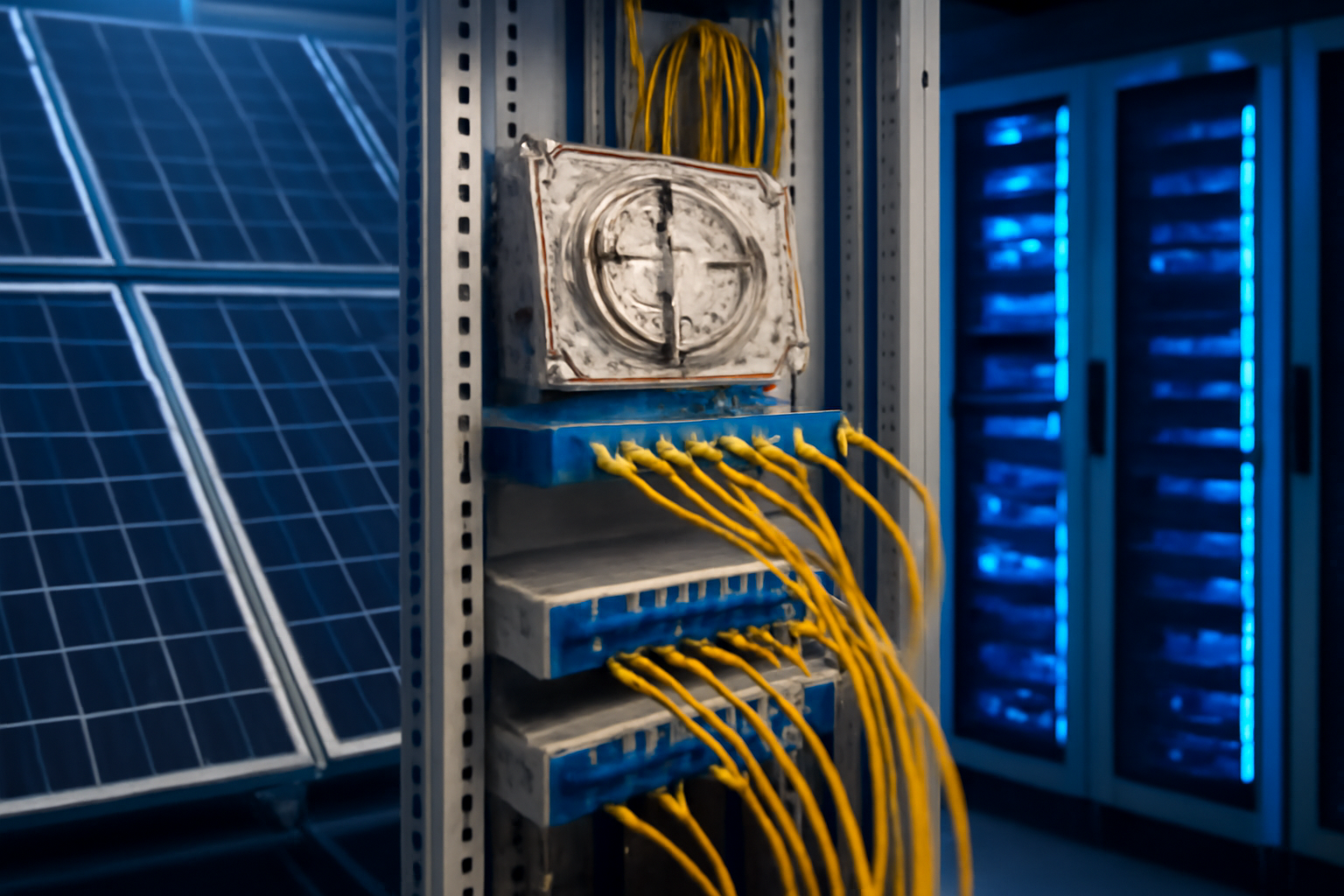
Solar park fibre optic systems, photovoltaic networks and optical fibre monitoring form the technical backbone of modern large-scale installations: optical fibres enable trouble-free data transmission over kilometres, redundant network topologies with switching times below 20ms and precise temperature monitoring via OTDR/BOTDR technology. The electromagnetic immunity of optical fibre makes it the ideal solution for the extreme conditions in solar parks – from inverter communication via SCADA systems to the integration of weather stations and security technology.
The new VDE guideline from February 2026 also simplifies installation considerably: optical fibre cables are classified as non-flammable and may be laid without expensive fire-rated conduits. For solar park operators and EPC service providers, this means significant cost advantages combined with higher availability through optical bypass functions.
Why Optical Fibre is the Superior Technology for Photovoltaic Networks
The physical properties of optical fibres predestine them for use in solar parks. Unlike copper cables, optical fibre connections are completely immune to electromagnetic interference caused by inverters with switching frequencies up to 20 kHz. A single singlemode fibre pair easily transmits 10 Gbit/s over 40 kilometres – sufficient to connect even the largest solar park clusters.
- No potential equalisation problems between spatially separated system sections
- Lightning strike protection without additional surge arresters
- Temperature resistance from −40°C to +70°C for outdoor deployment
- Bandwidth reserve for future expansions and AI-based analytics
- Integrated sensing via the fibre itself (Distributed Temperature Sensing)
Modern solar parks increasingly use ring topologies with automatic optical bypass. In case of cable damage – for example through mowing operations – the system switches to the redundant path within milliseconds. Availability rises to above 99.95%.
Technical Implementation: From Splice Box to Monitoring System
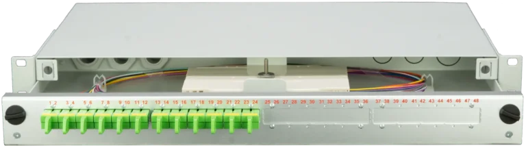
The optical fibre infrastructure of a solar park begins in the central handover station. Here the main lines from the network operator terminate in robust splice boxes, which serve as distribution points for park-internal networks. Typical configurations use 48 to 96 fibres in the main distribution, divided into different functional areas.
| Network Segment | Fibre Type | Bandwidth | Typical Application |
|---|---|---|---|
| Backbone | OS2 Singlemode | 10–100 Gbit/s | Control centre connection |
| Inverter Ring | OM4 Multimode | 1–10 Gbit/s | SCADA, Modbus TCP |
| Security Network | OS2 Singlemode | 1 Gbit/s | Cameras, access control |
| Sensor Network | OM3 Multimode | 100 Mbit/s | Weather stations, pyranometers |
In the decentralised distribution points, compact DIN rail enclosures with IP65 protection rating are used. These modular systems enable flexible termination of 12 to 24 fibres directly in the switch cabinet of the inverter stations.
Integration of OTDR and BOTDR for Precise Fault Location
Continuous monitoring of the optical fibre infrastructure is performed via Optical Time Domain Reflectometry (OTDR). Modern systems detect attenuation changes of less than 0.1 dB and pinpoint fault locations to one metre accuracy. For a typical park size of 100 hectares with 20 kilometres of optical fibre, this enables preventive maintenance before total failure occurs.
- Detection of gradual degradation caused by moisture or mechanical stress
- Documentation of attenuation values in compliance with IEC 61280-4-2
- Integration into existing SCADA systems via SNMP or Modbus
- Alerting when defined thresholds are exceeded via SMS or email
Fiber Products Quality Promise: As an official Diamond Partner and manufacturer, we produce modular splice systems in Europe. Benefit from Swiss precision and 5-year warranty on our systems.
Solar Park Fibre Optic in Practice: Redundancy Through Ring Topology
The failure safety of photovoltaic networks depends significantly on the chosen topology. Whilst star cabling leads to total failure when a cable breaks, ring structures with optical bypass guarantee uninterrupted communication. The optical fibre monitoring system automatically switches to the alternative path in case of faults – switching time is less than 20 milliseconds in accordance with IEEE 802.3.
A typical 50 MW solar park with 15 inverter stations uses the following redundancy architecture: the main ring connects all stations via two counter-directional fibre paths. Each station has an industrial Ethernet switch with SFP modules for optical fibre connection. In the event of a segment failure, data traffic automatically flows via the reverse direction.
| Redundancy Level | Availability | Switching Time | Additional Cost |
|---|---|---|---|
| Simple Star Topology | 98.5% | — | Base |
| Ring with Bypass | 99.95% | < 20ms | +35% |
| Dual Ring (RSTP) | 99.99% | < 50ms | +65% |
| Mesh Network | 99.995% | < 10ms | +120% |
Connector Types and Termination for Harsh Environmental Conditions
The choice of the right connectors determines the long-term stability of the photovoltaic network. Whilst standard LC connectors suffice in climate-controlled technical rooms, outdoor installations require more robust solutions. The E2000 connector to IEC 61754-15 with its spring-loaded protective shutter prevents the ingress of dust and moisture – ideal for distribution boxes in the field.
- LC Duplex: Compact form factor for high port density, up to 96 ports in 1U
- SC Simplex: Robust standard for industrial environments, easy to handle
- E2000 APC: Highest return loss >65dB, vibration-proof, IP65-suitable
- MPO/MTP: Parallel transmission with 12 or 24 fibres, ideal for backbone
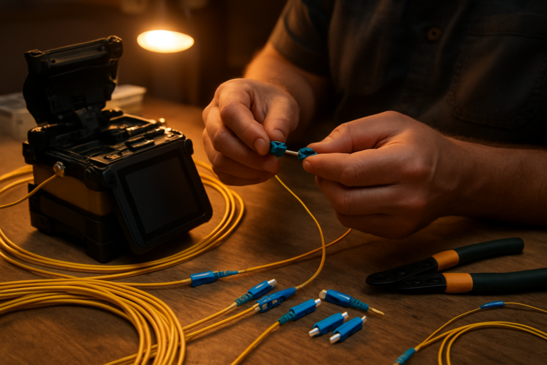
Pre-terminated patch cables and trunk cables are ideally manufactured off-site under clean-room conditions. On-site splicing should be minimised – each splice point introduces additional attenuation of 0.05 to 0.1 dB.
Standards and Regulations for Fibre Optic Installations in Solar Parks
The installation of solar park fibre optic systems is subject to strict standards that ensure quality and interoperability. DIN EN 50173-1 defines generic cabling structures, whilst IEC 61300 series specifies test procedures for connectors. Since February 2026, the new VDE guideline simplifies installation considerably: optical fibre cables are classified as non-flammable and no longer require separate fire-rated conduits.
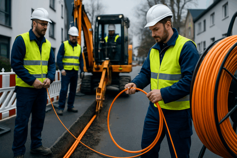
For outdoor deployment in solar parks, DIN VDE 0888-100 for optical fibre cables additionally applies. Cables must be UV-resistant, rodent-protected and suitable for direct ground burial. The minimum bending radii are 15 times the cable diameter under load and 10 times at rest.
Economics: ROI and Operating Cost Advantages
Investment in comprehensive optical fibre infrastructure typically pays for itself in solar parks within 3 to 5 years. Higher initial costs compared to copper cabling are offset by lower operating costs and higher availability. A 100 MW solar park saves approximately €45,000 annually in maintenance costs through optical fibre-based monitoring.
- No active repeaters required (energy savings)
- Fewer outages through preventive maintenance
- Reduced insurance premiums due to higher system reliability
- Future-proof for upcoming digitalisation requirements
- Integration of AI-based optimisation algorithms without network upgrades
Integration into Existing SCADA and Monitoring Systems
Modern SCADA systems for photovoltaic installations are based on open standards such as IEC 61850 and Modbus TCP. The optical fibre infrastructure transparently transports these protocols and enables real-time monitoring of all system parameters. Typical data rates per inverter are 1–10 Mbit/s, with the majority allocated to high-resolution power curves and event logs.
Integration is achieved via industrial Ethernet switches with optical fibre uplinks. These devices support Quality of Service (QoS) for prioritising critical control commands and VLAN segmentation for separating production and maintenance networks. Time synchronisation via Precision Time Protocol (PTP) achieves accuracy of below one microsecond over optical fibre.
| SCADA Function | Bandwidth | Latency Requirement | Priority |
|---|---|---|---|
| Emergency Shutdown | 1 kbit/s | < 10ms | Critical |
| Power Control | 100 kbit/s | < 100ms | High |
| Meter Data Collection | 1 Mbit/s | < 1s | Normal |
| Video Surveillance | 10 Mbit/s | < 5s | Low |
Future Trends: AI-Driven Optimisation and Predictive Maintenance
Next-generation optical fibre monitoring for solar parks uses artificial intelligence to detect patterns in fibre sensor data. Minor changes in attenuation or polarisation state indicate incipient degradation – long before conventional monitoring systems detect it. The EU AI Act classifies such systems as low-risk provided they are transparently documented.
The optical fibre itself becomes a distributed sensor: Brillouin scattering enables temperature measurement along the entire cable length with a resolution of one metre and ±1°C. Hot spots in cable ducts or overheated joints are detected immediately. This technology reduces unplanned outages by up to 60 per cent.
Practical Implementation: Checklist for Solar Park Operators
Successful implementation of an optical fibre infrastructure requires systematic planning. From needs analysis through procurement to commissioning, technical and economic aspects must be considered. The modular systems from Fiber Products with 5-year warranty provide maximum flexibility with the highest quality from European manufacturing.
- Inventory: number of inverters, distances, environmental conditions
- Network design: topology, redundancy, bandwidth dimensioning
- Material selection: cable types, connectors, distribution systems
- Installation: routing methods, splice plan, documentation per DIN EN 50174
- Commissioning: OTDR measurement and test equipment, attenuation budget, reporting
- Operation: monitoring integration, maintenance intervals, spare parts inventory
FAQ: Frequently Asked Questions on Solar Park Fibre Optic
What advantages does optical fibre offer over copper in solar parks?
Optical fibre is completely immune to electromagnetic interference from inverters, bridges distances up to 40 kilometres without amplifiers and offers bandwidth reserves for future expansions. Lightning protection and absence of potential coupling significantly increase system availability.
How complex is retrofitting existing installations?
Migration typically occurs in phases: the backbone is first converted to optical fibre, then critical connections follow. Modern media converters allow continued use of existing copper end devices. Upgrading a 10 MW installation typically takes 2 to 3 weeks without operational interruption.
Which connector types are suitable for outdoor installations?
The E2000 connector with protective shutter and robust SC connectors have proven themselves in practice. For backbone connections with high fibre counts, MPO/MTP connectors are used. All outdoor connectors should provide at least IP65 protection.
How are optical fibre cables protected against rodents?
Special outdoor cables feature glass yarn armour or metal sheath as rodent protection. Alternatively, cables are laid in protective ducts of PE or in cable trays. The additional cost of approximately 20 per cent is recovered through prevented repairs.
What bandwidth does a modern solar park require?
At least 10 Mbit/s symmetrical bandwidth per MW of installed capacity should be planned. A 100 MW park thus requires 1 Gbit/s for monitoring, control and additional services such as video surveillance. Optical fibre provides sufficient reserves for future requirements.
How is integration into existing energy management systems achieved?
Modern optical fibre infrastructures transparently transport all common protocols such as IEC 61850, Modbus TCP or OPC UA. Gateway solutions enable connection of proprietary systems. High bandwidth allows parallel data streams without mutual interference.
Summary and Outlook
Solar park fibre optic systems revolutionise the monitoring and control of large-scale photovoltaic installations. The combination of immunity to interference, unlimited bandwidth and integrated sensor functions makes optical fibre the key technology of the energy transition. With the new VDE guideline and falling component costs, optical fibre is becoming standard for professional solar parks.
As a European manufacturer and Diamond Partner, Fiber Products provides the complete system solution for your optical fibre infrastructure. From modular splice boxes to robust industrial enclosures and high-quality E2000 connectors – everything from a single source with 5-year warranty. Contact our experts for individual advice on your solar park project.
„`
Request a Quote
Do you have questions about our optical fibre solutions? Our expert team will advise you – free of charge and without obligation.