Edge Computing and Fibre Optics: Distributed Network Infrastructure 2026
Edge Computing and Fibre Optics: Distributed Network Infrastructure 2026
Edge Computing fundamentally changes the requirements for fibre optic infrastructure: decentralised Multi-access Edge Computing (MEC) architectures require fibre optic links with latency below 1 ms as the critical connection between local compute nodes and central data centres.
Technical Requirements for Edge Computing Fibre Optic Infrastructure
Implementation of MEC (Multi-access Edge Computing) infrastructure places specific demands on fibre optic technology. Modern edge nodes require singlemode fibres OS2 with minimal attenuation of < 0.25 dB/km at 1550nm for distances up to 40 kilometres between distributed sites. Connection technology must ensure the highest precision.
- Splice connections with < 0.02 dB attenuation per IEC 61300-3-4
- Connector terminations with < 0.3 dB insertion loss
- Return loss > 60 dB for APC connectors
- Temperature resistance -40°C to +85°C for industrial environments
- Vibration resistance per IEC 61300-2-1
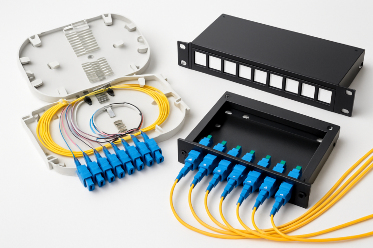
Physical infrastructure must be flexibly scalable. Modular splice systems enable stepwise expansion from initially 12 fibres to up to 288 fibres in 4RU, without interrupting existing connections.
Network Architecture for Decentralised Networks and Local Computing
The topology of a decentralised network for edge computing differs fundamentally from classical star topologies. Instead of central hubs, meshed structures emerge with local aggregation points. These require specialised fibre distribution systems.
| Network Layer | Fibre Count | Connector Type | Typical Distance | Loss Budget |
|---|---|---|---|---|
| Edge node to edge node | 12–24 fibres | LC-Duplex APC | < 5 km | < 2 dB |
| Edge to regional hub | 48–96 fibres | MPO/MTP-12 | 5–20 km | < 5 dB |
| Regional hub to data centre | 144–288 fibres | MPO-24 | 20–40 km | < 10 dB |
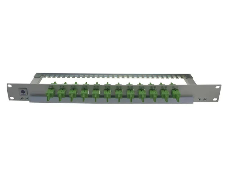
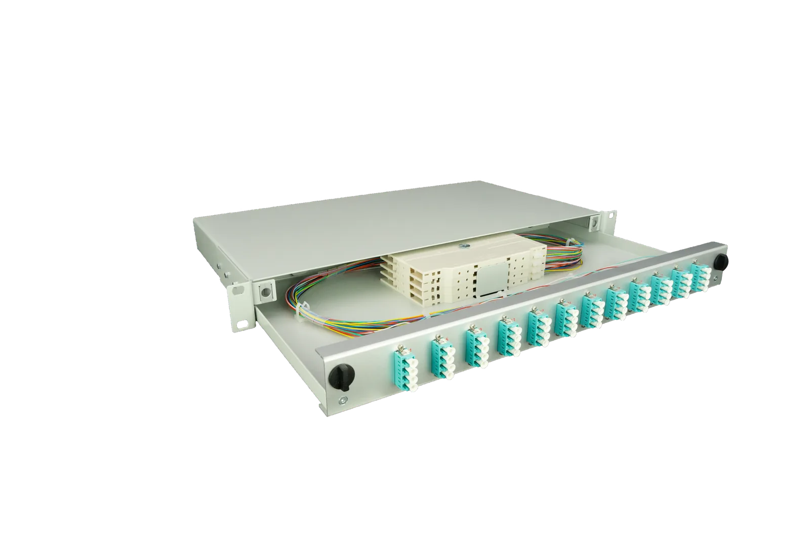
Each network layer requires adapted splice boxes with different capacities and connector types. The SlimConnect 1RU splice box is optimal for edge nodes with high port density in minimal space.
MEC Infrastructure Standards and Compliance
Standardisation of MEC infrastructure follows strict requirements from ETSI (European Telecommunications Standards Institute) and ITU-T. For fibre optic installations, the following core standards apply: ITU-T G.652.D for singlemode fibres, IEC 61754 for connectors and IEC 61300 for test procedures.
Fiber Products Quality Commitment: As an official Diamond Partner and manufacturer, we produce modular splice systems in Europe. Benefit from Swiss precision and 5 years warranty on our systems.
The new TKG Amendment 2026 also significantly simplifies approval procedures for fibre optic deployments in Germany. Fibre optic infrastructure is now classified as “outstanding public interest”, reducing planning and construction times by up to 40 per cent.
Practical Implementation: Edge Computing Fibre Optics in Industry
Industrial edge computing applications place particular demands on fibre optic infrastructure. In production environments with electromagnetic interference, E2000 connectors per IEC 61754-15 with their metallic protective cap and IP65 rating are essential.
- DIN rail mounting per DIN EN 60715 for control cabinets
- Operating temperature -25°C to +70°C without air conditioning
- Shock and vibration resistance per IEC 60068-2
- EMC compliance per EN 61000-6-2 for industrial environments
- Flame resistance UL94-V0 for enhanced fire safety
The modular design enables subsequent expansion without operational interruption. A typical industrial scenario starts with 12 fibres for sensor networks and grows stepwise to 48 fibres for video surveillance and real-time control.
Latency Optimisation Through Strategic Fibre Distribution
Minimising latency in edge computing networks requires precise planning of fibre routing. Each splice point adds 0.01–0.05 dB attenuation and 0.1–0.3 μs latency. For critical real-time applications with latency budgets below 5 ms, every microsecond counts.
| Connection Type | Attenuation | Latency Contribution | Recommended Count |
|---|---|---|---|
| Fusion splice | < 0.02 dB | < 0.1 μs | Max. 4 per link |
| LC-APC connector | < 0.3 dB | < 0.2 μs | Max. 6 per link |
| MPO-12 connector | < 0.35 dB | < 0.3 μs | Max. 2 per link |
Pre-terminated systems significantly reduce the number of splice points. The VarioConnect systems offer factory-terminated modules with guaranteed attenuation values.
Scaling Strategies for Growing MEC Infrastructure
Stepwise expansion of edge computing networks requires forward-looking planning of fibre capacity. Modern splice boxes must provide reserves for at least 50 per cent growth without affecting ongoing operations.
- Initial phase: 24 fibres for basic connectivity
- Expansion stage 1: 48 fibres for redundant paths
- Expansion stage 2: 96 fibres for multi-tenant scenarios
- Full expansion: Up to 288 fibres in 4RU for carrier-grade requirements
The modular architecture of SlimConnect and VarioConnect systems enables this scaling by simply inserting additional splice cassettes. Each cassette accommodates 24 fusion splices in a compact 130 x 90 mm footprint.
Integration of 5G Campus Networks with Fibre Backhaul
Private 5G campus networks require high-performance fibre connections for backhaul between radio cells and edge servers. Bandwidth requirements per 5G cell are 10–25 Gbit/s, requiring at least two singlemode fibres per site.
For connecting small cells in production halls, E2000 compact connectors have proven effective. Their robust design withstands vibration and electromagnetic interference, whilst the bayonet locking mechanism prevents accidental disconnection. As a Diamond Partner, Fiber Products offers the complete E2000 range in Swiss quality.
Redundancy Concepts for Highly Available Edge Networks
Critical edge computing applications require redundant fibre paths with automatic failover in case of faults. Implementation is via separate route paths with spatial diversity of at least 10 metres.
- Primary path: Direct connection with minimal latency
- Secondary path: Alternative route with < 20% higher latency
- Optical switch: Automatic failover in < 50 ms
- Monitoring: Continuous monitoring of attenuation values
- Alerting: SNMP traps on threshold exceeded
Splice reserves must be separately documented for both paths and housed in different splice boxes. This ensures maximum availability even during maintenance work.
Energy Efficiency and Sustainability in Distributed Networks
Edge computing fibre optics and decentralised MEC infrastructure contribute significantly to energy efficiency. Through local data processing, data transport to central data centres is reduced by up to 70 per cent, substantially lowering network infrastructure energy consumption.
Fibre optic cables themselves require no active cooling and have a lifespan exceeding 25 years. Passive components such as splice boxes and patch panels operate completely without power. Modern transceivers consuming < 3.5 watts per 10 Gbit/s further reduce the energy demands of active equipment.
Maintenance and Documentation of Edge Fibre Networks
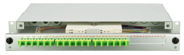
The complexity of distributed networks requires precise documentation of every fibre connection. Modern splice boxes integrate RFID tags and QR codes for digital record keeping. Documentation includes attenuation measurements per IEC 61280-4-1 and OTDR measurements for fault location.
| Maintenance Interval | Test Scope | Limit Value | Action if Exceeded |
|---|---|---|---|
| Monthly | Visual inspection of connectors | No contamination | Cleaning with isopropanol |
| Quarterly | Attenuation measurement | < 0.5 dB increase | Connector re-polishing |
| Annually | OTDR measurement | No new events | Fault location and repair |
Future Outlook: Edge Computing Fibre Optics 2026 and Beyond
The development of edge computing fibre optics and decentralised MEC infrastructure continues to accelerate. By 2028, experts expect 400G Ethernet as the standard for edge-to-edge connections. Fibre optic infrastructure must already be designed for these bandwidths today.
New fibre technologies such as multicore fibres with up to 19 cores per fibre will further increase packing density. Simultaneously, silicon photonics enable integration of optical functions directly into edge servers, further reducing latency.
- Hollow-core fibres: 30% faster signal propagation
- AI-based network optimisation: Automatic path adaptation
- Quantum key distribution: Tamper-proof connections
- Disaggregated networks: Open standards for interoperability
Practical Implementation: From Planning to Finished MEC Infrastructure
Implementation of edge computing fibre optic infrastructure follows a structured process. From needs analysis through network planning to final installation, a typical project takes 3–6 months. Fiber Products’ modular systems reduce installation time by up to 40 per cent compared to conventional solutions.
Module pre-termination occurs factory-side under clean room conditions. This guarantees consistent quality with attenuation values below 0.15 dB per connector. The 5 years warranty on all system components provides additional investment security for network operators and industrial enterprises.
FAQ: Frequently Asked Questions on Edge Computing and Fibre Infrastructure
How many fibres does a typical edge node require?
A standard edge node starts with 24 fibres — 12 for uplinks to the regional hub and 12 for local connections. As requirements grow, modular expansion to 48 or 96 fibres is possible.
How do APC and PC connectors differ for edge applications?
APC connectors (Angled Physical Contact) offer > 60 dB return loss, significantly better than PC connectors (45 dB). For latency-critical edge applications, APC connectors are therefore standard.
What loss margin should be planned for edge networks?
Plan for at least 3 dB loss margin for future expansion and ageing. For a typical 10G link budget of 13 dB, actual loss should not exceed 10 dB.
Are multimode fibres suitable for edge computing?
Multimode fibres (OM4/OM5) are suitable only for short distances under 400 metres within an edge site. For connections between edge nodes, singlemode fibres OS2 are mandatory.
How many splice reserves should be held per fibre?
At least 2 metres of splice reserve should be planned at both ends per fibre. This allows up to 4 re-splices without cable re-routing.
What temperature class is needed for industrial edge installations?
For unconditioned industrial environments, the extended temperature class I-temp (-40°C to +85°C) is required. Standard components (C-temp: 0°C to +70°C) are only suitable for air-conditioned areas.
Summary: Edge Computing Fibre Optics as Key Technology
Edge computing fibre optics and decentralised MEC infrastructure are developing into the technological backbone of digital transformation in Germany. With investments exceeding €4.2 billion in 2026 alone, a new generation of distributed data centres is emerging, based on high-density fibre optic systems.
Successful implementation requires well-considered system solutions — from robust splice boxes via precise connectors to scalable modularity. As manufacturer and Diamond Partner, Fiber Products supplies complete infrastructure from a single source, manufactured in Europe with 5 years warranty.
Contact our experts for tailored advice on your edge computing fibre optic infrastructure and benefit from over 20 years of experience in fibre optic technology.
Request a Quote
Have questions about our fibre optic solutions? Our expert team is happy to advise you — free and without obligation.