Fibre in Ducts: Blowing vs. Pulling – Installation Methods Compared
Fibre in Ducts: Blowing vs. Pulling – Installation Methods Compared
Choosing the right installation method for optical fibre cables in ducts significantly influences installation costs and long-term stability: blowing and pulling differ fundamentally in application scope, speed, and technical requirements.
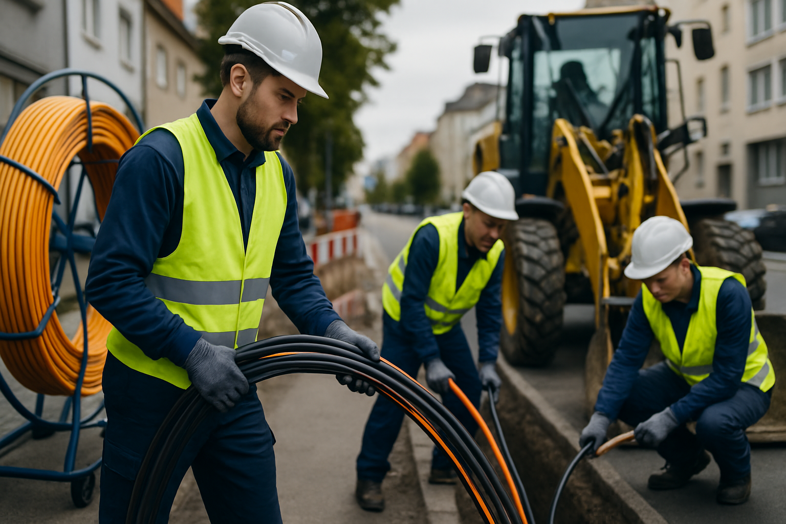
In German fibre rollouts, blowing technology increasingly dominates because it minimises cable damage and reduces installation time by up to 30 percent. Municipal utilities and network operators benefit from cost advantages of €1.00 to €1.50 per metre while achieving higher installation quality.
Technical Fundamentals: Blowing Fibre vs. Pulling Optical Fibre
The physical differences between both installation methods determine their fields of application. When blowing, a controlled air stream transports the optical fibre cable through the duct, minimising friction between cable jacket and duct inner wall. Pulling, by contrast, uses mechanical force via pulling sleeves or pull ropes.
| Criterion | Blowing (Jetting) | Pulling (Pulling) |
|---|---|---|
| Maximum span length | Up to 4,000 m | 500–800 m |
| Mechanical stress | Minimal (air cushion) | High (direct pull force) |
| Bend radii | 60 mm minimum | 150 mm recommended |
| Duct inner diameter | From 10 mm | From 25 mm |
| Installation cost/m | €1.00–1.50 | €2.50–4.00 |
Blowing technology requires special compressors with 13 to 15 bar pressure and air output of 1 to 3 m³/min. Modern equipment such as the AIRJET series integrates automatic crash tests to adjust thrust force and prevent cable jams in bends.
Duct Requirements for Optimal Installation Results
Duct quality determines installation success for both methods. Blowing places particularly strict demands on inner surface condition. Smooth inner walls without corrugation allow longer blowing spans, while corrugated ducts slow air flow.
- Inner diameter minimum 10 mm for microducts
- No corrugation or waviness of inner wall
- Bend radius minimum 60 mm when blowing
- Pressure resistance per DIN EN 50086
- Water-tightness for permanent cable protection
- UV resistance for above-ground installation
The ZTV-40 pressure test before blowing identifies duct damage and blockages. For network levels 2 and 3, this test is standard in municipal fibre rollouts. Civil works contractors document test results for later acceptance by utilities or network operators.
Blowing Fibre: Modern Installation Technology in Detail
The blowing method revolutionises fibre installation through gentle cable transport without mechanical pull stress. Air flow creates uniform thrust that propels the cable through the duct. This technique enables installation lengths up to 2,500 m in standard applications and up to 4,000 m under optimal conditions.
The technical equipment of modern blowing devices includes electronic thrust regulation, automatic speed adjustment, and integrated moisture separators. The DuoSync software coordinates feed and air pressure for maximum range with minimal cable stress.
Fiber Products Quality Promise: As an official Diamond partner and manufacturer, we produce splice boxes and splice modules in Europe. Benefit from Swiss precision and 5 years’ warranty on our systems.
Pulling Optical Fibre: Proven Method for Short Spans
Classical pulling remains indispensable for certain applications. For spans under 500 metres with straight route layouts, it offers advantages through simple handling without specialist equipment. Direct mechanical control enables precise work in confined spaces.
- Observe maximum pull force per manufacturer specification
- Distribute pulling sleeves evenly over at least 1 m cable length
- Use lubricant to reduce friction
- Maximum pull speed 20 m/min
- Continuous force measurement for critical spans
Mechanical stress when pulling requires reinforced cable designs with central pull elements. This increases cable costs and weight, which in turn reduces maximum possible pulling length.
Cost Comparison and Economics for Civils Contractors
Economic analysis shows clear advantages for blowing on spans over 500 metres. The initial investment in blowing equipment pays for itself through reduced labour time and fewer splice points within a few projects.
| Cost factor | Blowing | Pulling | Saving |
|---|---|---|---|
| Labour time per 1,000 m | 2–3 hours | 6–8 hours | 60% |
| Personnel | 2 technicians | 3–4 technicians | 40% |
| Splice points | Fewer due to longer spans | More connections required | 50% |
| Cable damage | < 1% | 3–5% | 80% |
Reduced splice points with blowing lower not only installation costs but also improve network quality. Each splice point means potential attenuation of 0.05 to 0.1 dB, which accumulates over long spans.
Practical Applications: Fibre Blowing, Optical Fibre Pulling, Duct Methods Compared
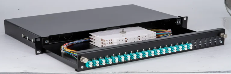
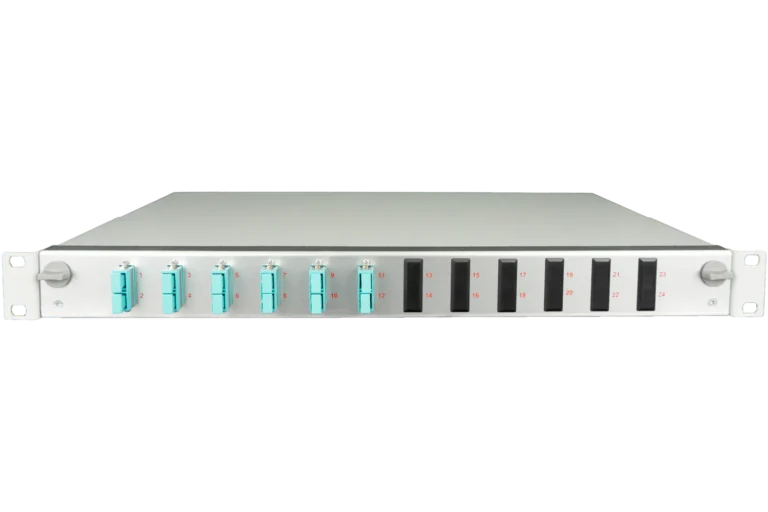
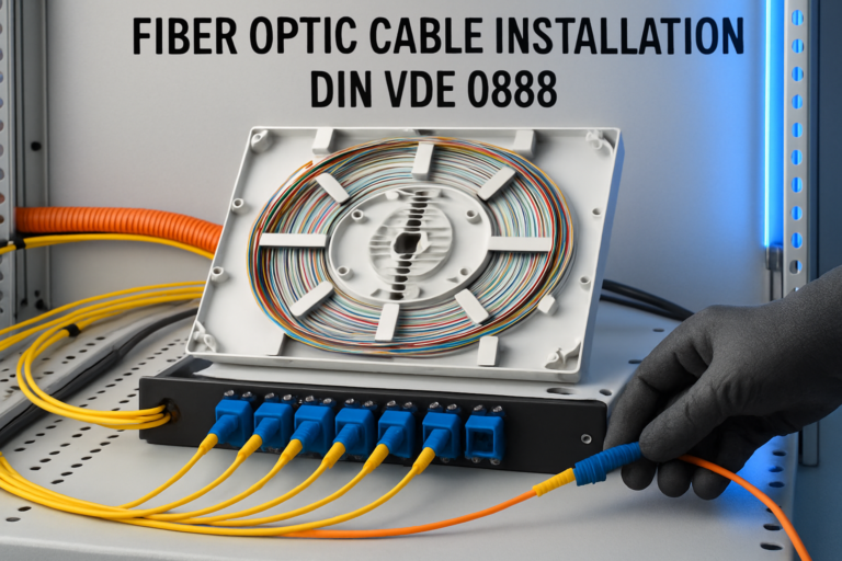
In municipal FTTH deployment, blowing dominates for backbone connections between distributors. Utilities rely on blowing spans of 1,500 to 2,000 m between network levels 3 and 4. Modular splice modules in distribution cabinets enable flexible fibre distribution with up to 96 fibres on 1 HU.
For in-building connections under 200 metres, pulling remains economical, especially with pre-terminated vs field installation. Direct installation from the distributor to the building often occurs in a single work phase during civil works.
- Backbone networks (NL2–NL3): Blowing up to 4 km, ducts 40–50 mm
- Distribution networks (NL3–NL4): Blowing 1–2 km, ducts 25–40 mm
- Building connections (NL4–NL5): Pulling or blowing < 500 m, microducts 10–14 mm
- Industrial facilities: Pulling with frequent direction changes
- Data centres: Blowing for structured cabling
Quality Assurance and Documentation to German Standards
The VDE 0800-730 defines new standards for building installation and simplifies documentation requirements. Civil works contractors must maintain installation records with span parameters, pressures used, and achieved lengths. OTDR measurement after installation documents attenuation values for each fibre.
Modern splice boxes integrate documentation fields for fibre allocation and measurement records. Diamond quality splice modules guarantee connector attenuation below 0.25 dB and return loss above 60 dB for APC connectors.
Future Trends: Automation and New Installation Techniques
Blowing technology continuously evolves. Electric drives increasingly replace pneumatic systems and offer more precise force control. Sensor integration enables real-time monitoring of cable position and automatic adjustment for obstacles.
- AI-supported route optimisation for maximum blowing spans
- Hybrid methods combining blowing and gentle push-through
- Microduct bundle installation for parallel fibre routes
- Temperature compensation in extreme weather conditions
- Digital twins document complete network infrastructure
Avoiding Common Errors: Tips from Practice
Experienced civils technicians know the critical points of both installation methods. With blowing, condensation in the compressed air system causes cable damage through freezing. Modern equipment therefore integrates coolers and moisture separators for air conditioning.
Uncontrolled blowing without crash-test function causes cable jams in bends. The automatic thrust adjustment in modern systems reduces force when resistance is detected to 0 to 100 percent and prevents damage.
When pulling, many technicians underestimate cumulative friction over long spans. Pull force increases exponentially with each direction change. Professional route planning with maximum three 90-degree bends per section optimises installation.
Specialist Applications: Fibre Blowing, Optical Fibre Pulling, Duct Methods in Industry
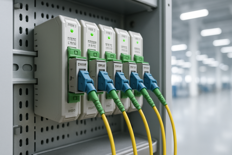
Industrial environments demand special installation techniques. Vibration-resistant E2000 connectors and IP65-rated DIN rail boxes require precise installation. Pulling offers advantages here through better control in confined switchgear cabinets.
| Industry sector | Preferred method | Specifics |
|---|---|---|
| Production halls | Blowing | Long straight spans, ducts 25–40 mm |
| Switchgear cabinets | Pulling | Short distances, tight radii |
| Outdoor installations | Blowing | Underground installation, PE ducts |
| Machine connection | Pulling | Flexible protective hoses |
Standards Compliance and Certification in DACH Region
Compliance with German and European standards ensures fibre installation quality. DIN EN 50173 defines structured cabling requirements, while IEC 61754 standardises connectors. Civil works contractors must consider both standard groups when selecting installation methods.
The ZTV Cable of the Research Society for Road and Transport Technology specifically regulates cable installation in public spaces. Utilities increasingly demand evidence of standards-compliant installation including pressure test records and OTDR measurements.
FAQ: Frequent Technical Questions on Fibre Blowing, Optical Fibre Pulling, Duct Methods
What maximum blowing length is realistic in 40 mm ducts with 8 mm cables?
Under optimal conditions with smooth ducts, you achieve 1,300 to 1,500 metres with modern blowing equipment at 7 to 10 bar pressure. Bends and height differences reduce reach proportionally.
How do I prevent condensation when blowing?
Integrated coolers and moisture separators in the blowing unit remove up to 95 percent of air humidity. Additionally, compressed air should be warmed to at least 5°C above ambient temperature.
When is pulling preferable despite shorter range?
For spans under 200 metres with pre-terminated cables, in existing buildings with many direction changes, or when retrofitting individual fibres into partially occupied ducts.
Which splice modules suit both installation methods?
Modular systems such as SlimConnect with 96 fibres on 1 HU offer flexible fibre accommodation independent of installation method. Interchangeable front plates support LC, SC, E2000, and MPO connectors.
How do I document installation to comply with standards?
Record installation date, method, achieved lengths, pressures or pull forces used, duct type and diameter, plus OTDR values. VDE 0800-730 specifies minimum requirements.
Can I blow microducts into existing, partially occupied ducts?
Yes, with specialised microduct blowing equipment and reduced pressure of 3 to 5 bar. Duct diameter should be at least 2.5 times the total cable diameter.
Conclusion: The Optimal Installation Method for Your Project
Fibre blowing, optical fibre pulling, duct method comparison – the decision depends on span length, route layout, and available infrastructure. Blowing dominates new installations over 500 metres through lower costs, higher speed, and minimal cable stress. Pulling remains relevant for short spans and existing buildings.
Modern fibre networks require well-planned installation concepts with suitable splice systems. As a manufacturer of modular fibre solutions, Fiber Products offers the complete system – from splice boxes to E2000 connectors in Swiss precision quality with 5 years’ warranty. Our Diamond partnership guarantees the highest manufacturing standards for lasting network quality.
Plan your next fibre project with the right installation technique and professional splice systems. Investment in high-quality components and the appropriate installation method pays off through reduced operational costs and greater network availability in the long term.
Request a Quote
Have questions about our fibre solutions? Our expert team is happy to advise you – free of charge and without obligation.