Fibre Optic Airport Networks – Infrastructure for Critical Aviation Systems
Fibre Optic Airport Networks – Infrastructure for Critical Aviation Systems
Fibre optic airport installations form the backbone of modern airport network systems and ensure uninterrupted data transmission for critical aviation applications – from air traffic control to baggage handling. The highly available fibre optic infrastructure connects over 500 different systems at a modern major airport, from boarding information displays through security cameras to radar and navigation systems. A single cable failure can, as the incident at Frankfurt Airport in 2023 demonstrated, paralyse hundreds of flights and trigger international chain reactions.
Critical Requirements for Fibre Optic Airport Systems
Aviation fibre optic infrastructure differs fundamentally from conventional office networks through its extreme availability requirements of 99.999% uptime. Every second of downtime means potential safety risks and massive financial losses. Modern airport network systems must therefore be designed with full redundancy and offer automatic switchover mechanisms in the millisecond range.
- Complete redundancy of all critical data paths with ring topologies
- Automatic switchover time in case of faults below 50ms
- Physical separation of main cable routes by at least 3 metres
- Fire protection classification per DIN 4102-12 for all cable routes
- Real-time monitoring of all routes using OTDR measurements
Bandwidth requirements are rising continuously: whilst 2015 still saw 10 Gbit/s backbone connections as standard, modern airports today require 100 Gbit/s for their main distributions. The integration of 4K video surveillance, biometric systems and artificial intelligence in particular is driving the demand for higher transmission rates.
Technical Architecture of Modern Airport Fibre Networks
Fibre optic airport architecture follows a hierarchical design with multiple security layers. At its core is the central data centre with fully redundant main distribution frames, from which fibre optic cables radiate in a star configuration to various terminals and operational areas.
| Network Layer | Fibre Type | Transmission Rate | Redundancy |
|---|---|---|---|
| Core Backbone | OS2 Singlemode | 100 Gbit/s | Dual ring structure |
| Terminal Distribution | OS2/OM4 | 40 Gbit/s | Redundant star configuration |
| Gate Connection | OM4 Multimode | 10 Gbit/s | Single connection with backup |
| Security Systems | OS2 Singlemode | 10–40 Gbit/s | Full redundancy |
Distribution points must withstand extreme environmental conditions. In baggage areas, temperature fluctuations range from −20°C to +50°C, whilst on the apron, vibrations from aircraft movements and electromagnetic interference from radar present additional challenges.
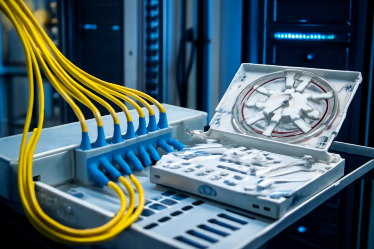
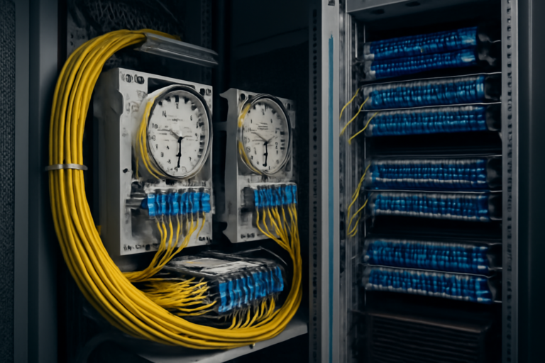
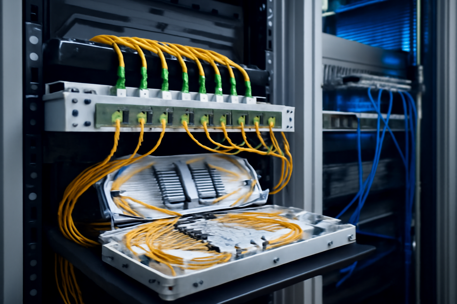
Splice Techniques and Connectivity for Airport Fibre Networks
The quality of splice connections is crucial to the reliability of the entire aviation fibre optic installation. Every single splice must exhibit attenuation of less than 0.1 dB and be documented. At a typical major airport with over 50,000 fibre splices, this means enormous effort for installation and maintenance.
- Use of fusion splice equipment with automatic alignment
- Splice protection via 60mm heat-shrink tubes with steel reinforcement
- Documentation of every connection with OTDR protocols
- Regular re-measurement on a six-monthly cycle
- Modular splice cassettes for 12 or 24 fibres per unit
Fiber Products Quality Promise: As an official Diamond partner and manufacturer, we produce modular splice systems in Europe. Benefit from Swiss precision and 5 years’ warranty on our systems.
Normative Requirements and Certifications
Fibre optic airport installations are subject to the strictest international and national regulations. The ICAO (International Civil Aviation Organization) together with the EASA (European Union Aviation Safety Agency) defines minimum requirements for critical communications systems. In Germany, the specifications of DFS (German Air Navigation Services) apply additionally.
| Standard/Norm | Application Area | Key Requirement |
|---|---|---|
| IEC 61754-15 | E2000 Connectors | Attenuation < 0.25 dB |
| EN 50173-1 | Structured Cabling | Categorisation of transmission routes |
| DIN VDE 0888-100 | Fibre Optic Cable | Fire behaviour, mechanical strength |
| ISO/IEC 11801 | Generic Cabling | Performance classes |
Particular importance attaches to aviation certification per ETSO for all safety-critical components. These European Technical Standard Orders require extensive testing under extreme conditions and complete traceability of all components.
Redundancy Concepts for Uninterrupted Operation
Airport network architecture is based on the principle of redundancy concepts for critical infrastructure, whereby at least one fully functional alternative route exists for every critical connection. Modern airports are increasingly adopting n+2 concepts to ensure full redundancy even during maintenance work.
- Geographically separated cable routes with minimum 30 metre spacing
- Independent power supply for active components via UPS and backup power
- Automatic switchover within 50 milliseconds
- Continuous monitoring via network management systems
- Quarterly redundancy tests under full load
A practical example: flight information displays are supplied via two independent fibre optic routes from separate server rooms. If one line fails, the second takes over seamlessly – passengers notice no interruption.
Specialised Applications of Aviation Fibre Optics
Fibre optic airport infrastructure supplies highly specialised systems with vastly different requirements. The ILS (Instrument Landing System), for instance, requires extremely stable connections with minimal latency, whilst baggage sorting systems demand high data rates for image processing.
Air Traffic Control Systems
Radar and navigation data are transmitted via dedicated singlemode fibres at wavelengths of 1310nm and 1550nm. Loss budgets are limited to a maximum of 0.35 dB/km to ensure safe transmission even over long distances to remote facilities.
Security Systems
Modern airports operate thousands of HD cameras whose video data are routed via OM4 multimode fibres to central recording systems. Each camera generates 25 Mbit/s, totalling several terabits in aggregate.
Passenger Systems
Check-in counters, gates and information terminals increasingly employ thin-client architectures where computing power is provided centrally. This reduces maintenance effort but significantly raises network quality requirements.
Installation and Commissioning
Installation of airport fibre network systems takes place in several phases and often must be performed during active flight operations. Night shifts and weekend work are standard to minimise disruption. A typical expansion project for a new terminal takes 12–18 months.
- Detailed route planning with 3D modelling of all cable paths
- Installation of main distribution frames with up to 2,000 ports per cabinet
- Cable laying in fire-protected ducts
- Splice work under four-eyes principle for quality assurance
- Acceptance testing per IEC 61280-4 standards
Particular challenges arise in security areas. Installers require background clearance, and all tools must be X-rayed. This extends working times by 30–40% compared to standard construction sites.
Maintenance and Operation of Fibre Optic Infrastructure
Preventive maintenance of aviation fibre optic systems follows rigorous maintenance plans analogous to aircraft maintenance. Annually, over 1,000 working hours are devoted to inspections and testing. Modern remote monitoring systems reduce effort, but cannot entirely replace physical inspections.
| Maintenance Interval | Activity | Effort |
|---|---|---|
| Daily | System monitoring | Automated |
| Monthly | Visual inspection of critical points | 8 hours |
| Quarterly | OTDR measurements main routes | 24 hours |
| Annually | Complete inspection of all connections | 120 hours |
Future Perspectives and Technological Developments
Fibre optic airport technology is evolving rapidly. 400 Gbit/s Ethernet is on the verge of introduction, whilst initial trials of terabit transmissions are underway. At the same time, wavelength division multiplexing (WDM) enables multiple use of existing fibres without new cable installation.
Emerging applications such as autonomous baggage vehicles, full-body biometric scanners and AI-driven security systems will further increase requirements. Experts anticipate a tenfold increase in data volume by 2030.
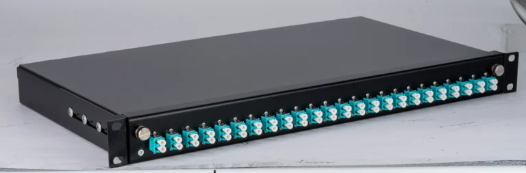
As a European manufacturer of modular splice systems, Fiber Products supports this development with future-proof solutions. Our SlimConnect 1HE systems accommodate up to 96 fibres in a single rack unit – double that of standard solutions. This creates valuable space in the often-crowded equipment rooms of airports.
Economic Considerations and Investment Planning
Investment in modern airport fibre network infrastructure pays back quickly despite high initial costs. A mid-sized airport typically invests €5–10 million in fibre optic infrastructure but saves €1–2 million annually through reduced maintenance effort and higher system availability.
- Reduction of unplanned outages by up to 90%
- Energy savings of 30–40% compared to copper cabling
- Future-proofing for at least 25 years
- Simplified expansion through modular systems
- Lower air-conditioning costs due to reduced heat generation
Practical Implementation Recommendations
For airport operators and system integrators, a phased expansion of aviation fibre optic infrastructure is recommended. Beginning with critical systems such as air traffic control and security technology, followed by passenger systems and finally comfort applications. Selecting high-quality, certified components with at least 5 years’ warranty ensures long-term operational stability.
Integration of existing copper networks is achieved via media converters during transition phases. Early training of maintenance personnel and building in-house expertise in fibre optic technology is important. Experience from government sector projects shows that well-trained teams resolve faults 60% faster.
FAQ on Fibre Optic Airport Installations
Which fibre types are suitable for airport environments?
For backbone connections, OS2 singlemode fibre with low attenuation is recommended. Inside buildings, OM4 multimode can be used for distances up to 500 metres. All cables must be halogen-free and flame-retardant per IEC 60332-3.
How are fibre optic cables protected from rodents?
Airports use special armoured cables with steel mesh or glass yarn reinforcement. Additionally, cable ducts are sealed and regularly inspected for damage. In critical areas, metal conduits are employed.
Which redundancy concepts are mandated for air traffic control systems?
EASA requires at minimum dual redundancy (n+1) for all safety-critical systems. This means two completely independent fibre optic routes with automatic switchover within 50 milliseconds.
How long does migration from copper to fibre take?
Complete technology transition during active operations typically takes 24–36 months. Migration occurs step-by-step according to priorities, with critical systems taking precedence. Comparable data centre projects show similar timeframes.
Which splice modules are suitable for airport equipment rooms?
Proven solutions include 19-inch systems with high packing density. Modules should be front-accessible and offer E2000 couplings for secure connections. The 5 years’ warranty provides additional investment security.
How is fibre optic quality continuously monitored?
Modern systems employ integrated OTDR modules for continuous route measurement. When attenuation changes exceed 0.5 dB, automatic alarms are triggered. Additionally, manual control measurements are performed quarterly.
Request a Quote Today
Have questions about our fibre optic solutions? Our expert team is happy to advise you – free and without obligation.