OTDR measurements: The complete guide to professional fiber optic quality assurance

Optical time domain reflectometry (OTDR) is at the heart of quality assurance in the fiber optic network. For municipal utilities, which are increasingly building and operating their own fiber optic infrastructures, the professional implementation of OTDR measurements is becoming a decisive success factor. This article shows in detail how municipal network operators can optimally use OTDR technology to inspect their networks in accordance with standards, precisely localize faults and ensure the highest quality in the long term.
The central role of OTDR measurement in the municipal fiber optic network
With the rapid expansion of fiber optic networks in Germany, municipal utilities are faced with the challenge of ensuring the quality of their growing infrastructure. OTDR measurements have established themselves as an indispensable tool for this. As 3 EDGE GmbH emphasizes: “Especially in the installation and maintenance of fibre optic networks, there is no way around qualified acceptance measurements and their documentation with the help of suitable OTDR testers.”
The importance of professional measurement technology is underlined by the complexity of modern fiber optic networks. The transmission behavior of fiber optic connections is influenced by a wide variety of factors – from splice connections and fiber optic connectors to mechanical stresses on the fiber itself. Each of these impairments shows a characteristic reflection signature that can only be recognized and evaluated by precise OTDR measurements.
For municipal utilities, this means: Investing in qualified personnel and modern measurement technology is not a cost factor, but a quality assurance measure that pays off in the long term. Faulty installations that are not detected during acceptance lead to expensive repairs and dissatisfied customers later on.
Understanding the basics of physics
The functional principle of optical time domain reflectometry
VIAVI Solutions explains the basics: “An OTDR contains a laser diode as a light source, a photodiode as a detector and a precise time base. The laser emits a pulse of light at a specific wavelength that propagates through the optical fiber to be tested.”
The measuring principle is based on two physical phenomena:
1 Rayleigh sc attering Rayleigh scattering is caused by microscopic irregularities in the glass material. A small portion of the injected light is continuously scattered in all directions, with a fraction returning to the source. As FS Community explains: “The Rayleigh scattering power depends on the wavelength of the transmitted signal: the shorter the wavelength, the higher the power.”
This backscattering makes it possible to measure the attenuation along the entire length of the fiber. The OTDR display shows this as a continuously decreasing curve – the further the light penetrates into the fiber, the weaker the backscattered signal becomes.
2 Fresnel refle ctions Fresnel reflections occur at discrete points where the refractive index changes abruptly – for example at connectors, splices or fiber breaks. VIAVI Solutions specifies: “He had determined the reflection coefficient (reflectance) as the ratio of the amplitude of the reflected light to the incident wave.”
These reflections appear in the OTDR trace as characteristic peaks whose height and shape allow conclusions to be drawn about the type of event.
The importance of the dead zone
A critical aspect of OTDR measurements is the so-called dead zone. FS Community explains: “A dead zone refers to the period of time during which the detector is temporarily blinded by a large amount of reflected light until it regenerates and can read light again.”
There are two types of dead zones:
- Event dead zone: The minimum distance between two events at which they can still be identified separately
- Attenuation dead zone: The distance after a reflective event until accurate attenuation measurements are possible again
Modern OTDR devices such as the 6420B described by Fibconet have minimal event dead zones of only 3 meters – a decisive advantage when measuring short distances or events that occur in close succession.
Standard-compliant implementation in accordance with DIN EN 61280-4-2
The current standards situation
DIN EN 61280-4-2 is the definitive standard for OTDR measurements on single-mode optical fibers. As the VDE publishing house explains, this standard is “applicable to the measurement of attenuation and optical return loss of installed single-mode fiber optic cable systems.”
The current version of 2024 brings important innovations:
- Procedure with device cables was added
- Test limit values were adjusted with regard to the test cable qualities
- Measurement uncertainties have been refined
For municipal utilities, this means Existing measurement procedures must be reviewed and adapted if necessary. As the VDE publishing house emphasizes, the standard affects “planning offices and tradesmen who tender attenuation measurements using power meters or OTDR devices, carry out measurements or check measurement protocols for the purpose of acceptance documentation.”
Measurement set-up and pre-fiber
A standard-compliant OTDR measurement setup requires the use of leading and trailing fibres. elektro.net explains the necessity: “In order to be able to characterize the fibre end, you need a trailing fibre and an OTDR with sufficient dynamics.”
The pre-fiber fulfills several important functions:
- Bridging the dead zone of the first connector
- Protection of the OTDR connection against dirt and wear and tear
- Enabling the characterization of the first connector of the measuring section
3 EDGE GmbH offers special “pre-fiber/post-fiber for OTDR measurements according to IEC standard for bridging the event dead zones and for protecting the device connectors”.
Parameter setting for precise measurements
The correct setting of the OTDR parameters is crucial for meaningful OTDR measurements. elektro.net provides detailed recommendations:
Measuring range: “The measuring range should always be longer than the leading fiber + measuring section + trailing fiber. The noise behind the trailing fiber must be clearly visible.”
Pulse width: “The smaller the pulse width, the higher the resolution of the OTDR.” Modern devices offer pulses from 3 ns, which enables event dead zones of just 0.3 m. However, shorter pulses mean lower dynamics.
Wavelength: For single-mode fibers, measurements at 1310 nm and 1550 nm are standard. At longer wavelengths, Rayleigh scattering decreases, which leads to a better signal-to-noise ratio.
Averaging: FS Community recommends: “Normally 16 to 64 averages are sufficient.” More averages improve the signal-to-noise ratio, but increase the measurement time.
Practical implementation for municipal utilities
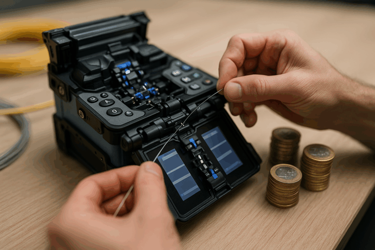
Step 1: Preparation and cleaning
RubyTech Deutschland emphasizes the importance of preparation: “At RubyTech Deutschland GmbH, an OTDR test involves inspecting the fibre optic connectors with a video inspection microscope, looking at the connector end faces, cleaning them with high-purity alcohol and a microfibre tape cartridge.”
This cleaning is essential, as dirty connectors are one of the most common sources of errors in OTDR measurements. Even microscopically small particles can lead to increased attenuation values or reflections.
Step 2: Carrying out the measurement
The actual measurement follows a structured procedure:
- Connection of the launch fiber to the OTDR
- Connection of the leader fiber to the section to be measured
- Connection of the trailing fiber at the end of the line
- Parameter setting according to the route requirements
- Start of measurement and averaging
- Storage of measurement data with unique designation
Fast Removement GmbH describes the measurement process: “In OTDR measurement, a special measuring device, the OTDR, sends short laser pulses with different wavelengths into the fiber optic cable. The device then measures exactly how long the light has been traveling.”
Step 3: Evaluation and interpretation
The interpretation of OTDR curves requires experience and specialist knowledge. Typical events and their representation:
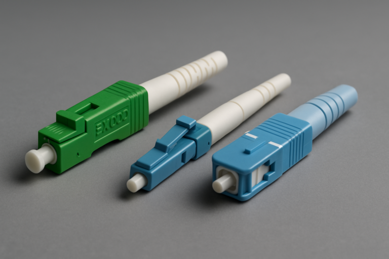
Connector: Appears as a clear reflection peak with subsequent attenuation step
Good splices: Show only a small attenuation level without reflection
Poor splices: Can exhibit both attenuation and reflection
Bends: Appear as increased attenuation without reflection
Fiber breaks: Show a high reflection with an abrupt end of the curve
3 EDGE GmbH explains: “The above view of the measurement results simplifies the reading of an OTDR curve by displaying symbols linearly for each wavelength.”
Bidirectional measurements for maximum precision
VIAVI Solutions recommends bidirectional OTDR tests for critical applications: “In these bidirectional OTDR tests, the optical fiber is characterized from both fiber ends and the attenuation is measured.”
The advantages of bidirectional OTDR measurements:
- Compensation for different backscatter coefficients
- Detection of events in the dead zone
- More accurate attenuation values through averaging
- Better characterization of very long distances
This method is particularly recommended for municipal utilities with critical backbone connections or important business customers.
Quality assurance and documentation
Professional acceptance reports
The documentation of the measurement results is just as important as the measurement itself. Fast Removement emphasizes: “You will receive a complete OTDR measurement protocol.”
A professional measurement protocol for OTDR measurements should include
- Date and time of the measurement
- Name of the measurement technician
- Unique route designation
- Measuring devices and serial numbers used
- Set measurement parameters
- Graphical representation of the OTDR curves
- Tabular listing of all events
- Pass/fail evaluation according to specification
- Signature of the responsible technician
Integration into quality management
For municipal utilities, the integration of OTDR measurements into a comprehensive quality management system is recommended. This includes
Standardized measurement procedures: Documented work instructions for all measurement technicians
Regular training courses: As offered by fiberHELP, based on “DIN EN 61280-4-2, DIN ISO/IEC 14763-3 and ZTV-43”
Device calibration: Regular inspection and calibration of all measuring devices
Database systems: Central storage of all measurement logs for later comparisons
Modern OTDR technology for municipal grid operators
Selection criteria for OTDR measuring devices
When selecting an OTDR system, municipal utilities should consider the following criteria:
Dynamic range: Determines the maximum measurable path length. For municipal networks, 28-35 dB is usually sufficient.
Dead zone: The smaller, the better for measuring short distances. Modern devices achieve event dead zones of less than 1 meter.
Wavelengths: At least 1310/1550 nm for singlemode. For special applications also 1625 nm or 1650 nm.
Ease of use: Intuitive touchscreen interfaces and automatic measurement functions increase efficiency.
Connectivity: USB, Ethernet or WLAN for easy data transfer.
Combined measuring devices for comprehensive tests
Modern OTDR systems often offer additional functions. The Fibconet 6420B, for example, integrates “automatic OTDR, expert OTDR, event card, optical power meter (OPM), visual fault locator (VFL).”
This multifunctionality offers advantages:
- Reduced number of devices to be carried
- Consistent operation across all measuring functions
- Integrated documentation of all measurements
- Cost efficiency through multiple use
Troubleshooting and troubleshooting
Recognize typical error patterns
Experience shows typical error patterns in municipal fiber optic networks:
High attenuation on plug connections
- Cause: soiling, poor plug quality, incompatible plug types
- Solution: Cleaning, replacement, use of high-quality components
Increased track damping
- Cause: Microbending due to improper installation
- Solution: Checking the installation, compliance with the bending radii
Unexpected reflections
- Cause: Damaged plugs, air gaps, incorrect plug types
- Solution: Inspection with microscope, reworking or replacement
Systematic troubleshooting
Fast Removement describes the efficiency: “The position and type of abnormalities can therefore be determined precisely.”
A systematic approach to OTDR measurements includes:
- Comparison with reference measurements: Identify deviations from the baseline
- Wavelength comparison: Different attenuation at different wavelengths indicates specific problems
- Bidirectional analysis: Recognizing directional effects
- Segment-by-segment testing: narrow down the problem area by measuring at intermediate points
Best practices for municipal network operators
Organizational recommendations
1. qualified personnel The Potsdam Chamber of Crafts offers special training courses: “This practice-oriented certificate course provides you with the necessary knowledge and basic skills to professionally carry out control measurements on hard-wired fiber optic components.”
2. standardized processes
- Standardized measurement procedures for all technicians
- Checklists for measurement procedures
- Defined limit values and acceptance criteria
3. continuous training Technology is constantly evolving. Regular training courses, such as those offered by ANEDiS, keep staff up to date.
Technical recommendations
1. investment in quality High-quality measuring devices and accessories pay off in the long term. The accuracy of OTDR measurements and the reliability of the devices justify higher acquisition costs.
2. preventive maintenance of the measuring devices
- Regular calibration according to manufacturer’s specifications
- Careful cleaning of the appliance connections
- Proper storage and transportation
3. comprehensive documentation Fluke Networks emphasizes: “However, characterizing the entire connection via an OTDR trace during the initial tests offers several advantages for both the technician and the customer.”
Future prospects and new developments
Integration into automated systems
The future lies in the integration of OTDR measurements into higher-level management systems. Automated test sequences, remote OTDR systems and AI-supported evaluations will further increase efficiency.
PON-specific measurement methods
With the expansion of PON networks (Passive Optical Networks), special measurement methods are becoming increasingly important. DIN EN IEC 61280-4-3 defines specific procedures for these network architectures, including filtered OTDR measurements (FOTDR) in the U-band.
Extended analysis options
Modern software enables ever more detailed analyses:
- Automatic event detection and classification
- Trending analyses for the early detection of creeping deterioration
- Integration with GIS systems for geographic fault visualization
Profitability and ROI
Investment analysis
The purchase of professional OTDR systems represents a considerable investment:
- Entry-level devices: 5,000 – 10,000 euros
- Professional systems: 15,000 – 30,000 euros
- High-end systems with extended functions: over 40,000 euros
There are also costs for:
- Training and certifications
- Calibration and maintenance
- Software updates and licenses
Return on investment
The investment in OTDR measurements pays for itself:
Avoidance of rework: Errors are detected during installation
Reduced downtimes: Fast and precise fault localization
Higher customer satisfaction: reliable networks lead to fewer complaints
Competitive advantages: Proof of professional quality assurance
Fast Removement summarizes: “A professional inspection of the pipe system saves you money, as faults can be detected at an early stage.”
Practical case studies
Stadtwerk Musterstadt: Systematic network qualification
Initial situation:
- 15,000 planned FTTH connections over 3 years
- External installation company
- High quality requirements from customers
- Necessity of standard-compliant acceptance
Implementation:
- Acquisition of 3 professional OTDR systems
- Training of 8 technicians according to DIN EN 61280-4-2
- Development of standardized measurement methods
- Development of digital documentation systems
Results after 18 months:
- 99.2% of all lines conform to standards at initial acceptance
- 75% reduction in rework
- 40% faster troubleshooting in the event of faults
- 95% customer satisfaction with new connections
Energy supplier RegioNet: Proactive grid monitoring
Challenge:
- 200 km backbone fiber optic network
- Critical business customer routes
- Preventive maintenance to avoid breakdowns
- Integration in network management system
OTDR strategy:
- Quarterly OTDR measurements of all critical routes
- Trending analysis for early detection of deterioration
- Automated alarm when limit values are exceeded
- Bidirectional measurements for maximum precision
Success:
- 60% reduction in unplanned downtime
- Early detection of 23 potential problems
- Optimized maintenance planning through trend data
- ROI break-even after 24 months
Integration with Fiber Products solutions
Optimized components for precise measurements
High-quality passive components are essential for reliable OTDR measurements. Our splice boxes and modular systems have been specially developed to minimize reflections and ensure reproducible measurement results.
Metrological advantages:
- Minimal reflections at connection points
- Precise damping values thanks to high-quality components
- Reproducible measurements over the entire service life
- Standard-compliant design for legally compliant approvals
Documented quality for reliable baselines
Each Fiber Products system is supplied with comprehensive documentation that serves as a reference for subsequent OTDR measurements. The 5-year warranty underlines the confidence in long-term stable measurement values.
Quality assurance:
- Factory testing of all critical parameters
- Traceable documentation of each component
- Consistent quality for reliable comparative measurements
- European production according to German quality standards
Conclusion: OTDR as a cornerstone of network quality
OTDR measurements are far more than a technical necessity – they are the cornerstone for the quality of municipal fiber optic networks. Municipal utilities and network operators that invest in professional measurement technology, qualified personnel and standardized processes create the basis for reliable and future-proof infrastructures.
Key benefits of professional OTDR measurements:
Quality assurance:
- Standard-compliant acceptance in accordance with DIN EN 61280-4-2
- Early detection of installation errors
- Precise fault localization in the event of malfunctions
- Long-term network monitoring through trend analyses
Economic advantages:
- Avoidance of costly rework
- Reduced downtime thanks to rapid diagnosis
- Higher customer satisfaction and retention
- Competitive advantages through verifiable quality
Legal certainty:
- Compliance with current norms and standards
- Documented acceptance protocols
- Traceable quality assurance
- Protection against warranty claims
Compliance with current standards, in particular DIN EN 61280-4-2, guarantees not only technical excellence but also legal security. In a market that is increasingly characterized by quality and reliability, professional OTDR measurements are becoming a decisive differentiator.
High-quality and reliable network components are essential for the practical implementation of professional OTDR measurements. The modular fiber optic systems from Fiber Products have been specially developed to meet the high demands of municipal network operators. Thanks to their precise processing and consistent compliance with all relevant standards, they enable reproducible measurement results and minimize reflections at connection points.
The exceptional 5-year guarantee underlines the confidence in the long-term stability – an important factor for meaningful comparative measurements over the entire service life of the network. With European production to German quality standards, we offer the reliability that professional OTDR measurements require.
Discover our complete product range or visit our online store. Talk to us – together we will develop the optimal strategy for your fiber optic quality assurance. Contact us for an individual consultation or find out more about other specialist topics in our fiber optic knowledge blog.