Fibre Optic Emergency Control Centres – Network Infrastructure for Life-Saving Communication
Fibre Optic Emergency Control Centres – Network Infrastructure for Life-Saving Communication
Emergency control centre fibre optic, emergency call 112 infrastructure and control centre optical fibre form the technical backbone of modern emergency communication – redundant fibre optic networks with < 0.25 dB attenuation and modular splice systems ensure uninterrupted connections between control centres, emergency services and hospitals. Critical infrastructure demands maximum availability of 99.999%, achievable only through professional optical fibre cabling with certified components to IEC 61754-15.
With the new VDE guideline 0800-730 (February 2026), fibre optic deployment in control centre buildings is significantly simplified. Optical fibre cables are now classified as fire-free and may be routed without costly fire protection conduits in escape routes – a decisive advance for rapid modernisation of existing emergency call centres.
Technical Requirements for Fibre Optic Networks in Integrated Control Centres
Integrated control centres coordinate thousands of emergency calls daily via the unified number 112. The underlying emergency call 112 infrastructure is based on high-availability fibre optic connections spanning multiple technical layers.
- Primary fibre optic connection with 10 Gbit/s to backbone network
- Secondary redundancy path via physically separated routes
- Internal networking with Singlemode OS2 fibres for distances up to 40 km
- Multimode OM4/OM5 for in-building connections up to 550 m
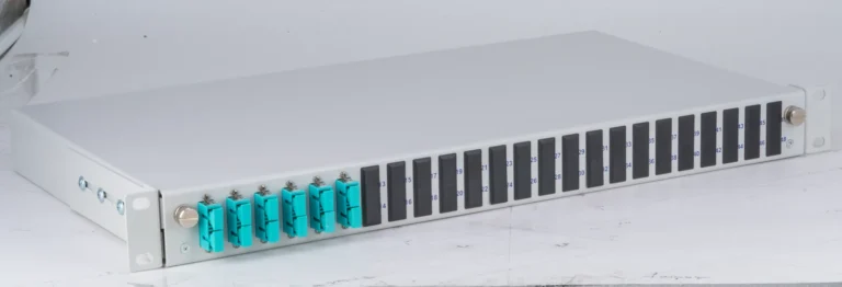
- Modular splice systems with up to 96 fibres on 1RU
The Federal Network Agency requires in its January 2026 concept a minimum FTTH coverage of 80% before any copper decommissioning. This directly affects all control centres still connected via obsolete copper lines.
Building Redundant Optical Fibre Systems for Emergency Call Centres
Control centre optical fibre systems must be designed according to the principle of dual redundancy. Every critical connection is physically duplicated and routed via separate paths.
| System Level | Primary Path | Redundancy | Availability |
|---|---|---|---|
| Backbone Connection | Main Route A | Route B (separate civil works) | 99.999% |
| Building Distribution | Riser North | Riser South | 99.99% |
| Floor Distribution | Main Frame | Secondary Frame | 99.95% |
| Workplace Connection | Port 1-48 | Port 49-96 | 99.9% |
The modular design enables rapid switchover in case of faults. With pre-configured splice modules, mean time to repair (MTTR) is reduced to under 15 minutes.
Splice Modules and Distribution Systems in Control Centre Technology
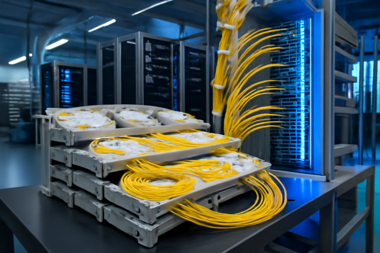
Modern emergency control centre fibre optic installations deploy high-density splice modules that manage large quantities of fibres in compact spaces. Distribution system requirements are particularly stringent.
- Vibration-resistant design to IEC 61587-1 for seismic zones
- Dust protection IP54 for sensitive electronics environments
- Colour coding per DIN VDE 0888 for rapid fault identification
- Documentation system with unique labelling for each fibre
- Strain relief for cables up to 48 fibres per module
Fiber Products Quality Promise: As an official Diamond Partner and manufacturer, we produce modular splice systems in Europe. Benefit from Swiss precision and 5 years’ warranty on our systems.
Standards-Compliant Installation per VDE 0800-730
The new VDE guideline transforms installation of control centre optical fibre in existing buildings. Optical fibre cables may now be routed without additional fire protection measures, delivering significant cost and time savings.
Technical installers benefit from simplified installation methods. Adhesive mounting enables direct fastening to walls and ceilings without elaborate cable ducts. The following standards must be observed during planning:
- DIN EN 50173-1 for structured cabling
- DIN EN 50174-2 for installation in buildings
- IEC 61300-3-35 for attenuation measurements
- ISO/IEC 14763-3 for acceptance documentation
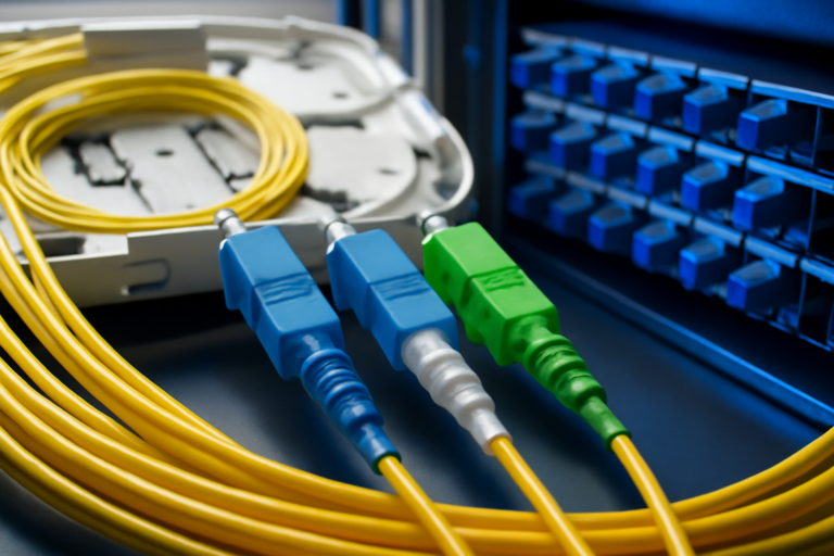
Connector Types and Connection Technology for Maximum Reliability
Selecting the correct connectors determines long-term stability of the emergency call 112 infrastructure. Control centres employ various connector types depending on requirements.
| Connector Type | Application | Attenuation | Special Feature |
|---|---|---|---|
| E2000 APC | Critical connections | < 0.1 dB | Protective shutter, vibration-resistant |
| LC Duplex | Standard cabling | < 0.25 dB | High packing density |
| SC Simplex | Existing networks | < 0.3 dB | Robust, proven |
| MPO/MTP | Backbone | < 0.35 dB | 12-24 fibres in parallel |
The E2000 connector has become the standard in safety-critical environments. The integrated protective shutter prevents contamination, whilst the ceramic ferrule ensures precise connections with minimal return loss.
Migration from Copper to Fibre Optic in Existing Control Centres
Upgrading existing emergency control centre fibre optic infrastructure requires careful planning. During ongoing operations, no outages can be tolerated – every second counts in emergency coordination.
- Parallel operation of copper and fibre optic during transition phase
- Gradual migration of individual workstations
- Test operation with 24-hour monitoring
- Training of technical staff for optical fibre maintenance
- Building spare parts inventory with pre-configured modules
Upon completion of migration, a future-proof infrastructure with transmission rates of 10 Gbit/s to 100 Gbit/s is available. The investment pays for itself through reduced maintenance costs and higher system availability within three to five years.
Maintenance and Fault Management in 24/7 Operation
Control centre optical fibre networks must be available round the clock. Professional maintenance planning encompasses preventive measures and rapid response times in case of faults.
Regular cleaning of connectors with specialised cleaning tools prevents gradual attenuation increase. Modern OTDR test instruments continuously monitor all fibre paths and alert to anomalies before they cause outages.
- Quarterly attenuation measurements of all routes
- Annual thermography for early detection of hotspots
- Documentation of all measurements in maintenance log
- On-call service with 30-minute response time
- Stock of critical components on site
Scalable System Architecture for Growing Demands
Requirements for emergency call 112 infrastructure grow continuously. New services such as NG-eCall for connected vehicles or integration of drone operations demand flexible fibre optic architectures.
Modular splice systems allow simple expansion of existing installations. With SlimConnect systems, up to 96 fibres can be terminated in just 1RU – double the density of conventional solutions. For larger control centres, VarioConnect systems accommodate up to 288 fibres in 3RU.
| System Type | Rack Units | Max. Fibres | Application |
|---|---|---|---|
| SlimConnect | 1RU | 96 | Small/medium control centres |
| VarioConnect | 3RU | 288 | Large control centres |
| VarioConnect XL | 4RU | 384 | Integrated control centres |
Quality Assurance and Acceptance Tests per IEC Standards
Acceptance of an emergency control centre fibre optic installation follows strict international standards. Every individual fibre is measured and documented.
Attenuation measurements must comply with limits in IEC 61280-4-1. For singlemode fibres, the limit is 0.4 dB/km at 1310 nm and 0.3 dB/km at 1550 nm. Return loss is also measured, with APC connectors requiring a minimum of 60 dB.
- Visual inspection of all connectors with video microscope
- Bidirectional OTDR measurement of each route
- Chromatic dispersion test for high-speed connections
- Polarisation mode dispersion for routes exceeding 10 km
- Generation of digital test report per ISO/IEC 14763-3
Grants and Financing for Municipal Fibre Optic Projects
Municipalities can utilise various funding programmes for expansion of control centre optical fibre infrastructure. The Federal Grey Spot programme alone provides over 2 billion euros for 2026.
Subsidy rates reach up to 90% of eligible costs for municipal operators. The prerequisite is undersupply with less than 100 Mbit/s in current state. Control centres receive special priority as critical infrastructure.
Future Perspectives: 6G Connectivity and AI Integration
The next generation of emergency call 112 infrastructure will be shaped by artificial intelligence and 6G mobile technology. Fibre optic networks form the essential backbone for terabit-rate data transmission.
New installations should be prepared for these requirements today. Installation of hollow-core fibres or pre-provisioning for wavelength division multiplexing (WDM) secures your investment for the next 20 years.
FAQ: Frequently Asked Questions on Fibre Optic in Emergency Control Centres
Which standards specifically apply to control centre optical fibre after 2026?
From February 2026, VDE guideline 0800-730 applies to building installations. Additionally, DIN EN 50173-1 for structured cabling and the IEC 61754 series for connectors are relevant. Control centres must also meet requirements of TR Emergency Call 2.0 for IP-based emergency call systems.
How does copper decommissioning affect existing emergency call infrastructure?
The Federal Network Agency requires FTTH coverage of at least 80% before any copper decommissioning. Control centres, as critical infrastructure, have priority in fibre optic expansion. Migration must be uninterrupted via parallel operation.
What advantages do E2000 connectors offer over LC in control centres?
E2000 connectors feature an integrated protective shutter preventing contamination. Attenuation at < 0.1 dB is lower than LC connectors. Vibration resistance per IEC 61753-1 makes them ideal for safety-critical applications.
How many fibres should a modern control centre provision?
A medium control centre requires at least 48 active fibres plus 100% reserve. Large integrated control centres plan with 192 to 384 fibres for main connections and internal networking. Modular design allows subsequent expansions.
What maintenance intervals are prescribed for control centre fibre optic networks?
DIN VDE 0800-770 recommends quarterly visual inspections and annual measurements. For critical connections, continuous monitoring with OTDR systems should be employed. Connector cleaning occurs as needed, but at least twice yearly.
Can existing multimode installations be continued for modern control centres?
Multimode fibres of category OM3/OM4 support 10 Gbit/s up to 550 metres. However, for new installations singlemode OS2 is recommended for future-proof transmission rates up to 100 Gbit/s and distances up to 40 kilometres.
Professional planning and installation of emergency control centre fibre optic systems requires specialised components of the highest quality. Fiber Products, as manufacturer and Diamond Partner, provides complete system solutions from one source – from modular splice systems through E2000 connectors to custom distribution solutions. With 5 years’ warranty and European production, we set standards for critical infrastructure. Our SlimConnect 1RU splice boxes deliver up to 96 fibres with the highest packing density on the market – ideal for space-critical control centre environments.
‟
Request a Quote
Do you have questions about our fibre optic solutions? Our expert team is happy to advise you – free of charge and without obligation.