Emergency Control Centre Fibre Optics – High-Availability Networking for Emergency Call Handling
Emergency Control Centre Fibre Optics – High-Availability Networking for Emergency Call Handling
Emergency control centre fibre optics, emergency call networks and control centre connectivity form the technical backbone of modern emergency response chains. With up to 31.5 million emergency calls annually, German control centres require high-availability fibre connections for real-time data transmission, automatic location identification and resilient communications. The transition to IP-based emergency call systems and the introduction of Advanced Mobile Location (AML) require redundant FTTH infrastructure with 99.999% availability across all 380 German fire and police control centres.
Technical Requirements for Emergency Control Centre Fibre Infrastructure
The modernisation of emergency call technology places the highest demands on fibre cabling in control centres. With the migration from 2G technology to IP-based 4G/5G networks and the introduction of Next Generation Emergency Call (NG eCall) from January 2026, data volumes are growing exponentially.
Modern control centre networking must handle the following data streams:
- Real-time location data (AML) for emergency numbers 112 and 110 across 13 federal states
- NG eCall data streams with live images and vehicle telemetry data
- Real Time Text (RTT) for deaf and speech-impaired persons from 2027
- Emergency response software data with direct transmission to hospitals
- 155,000 automatic eCalls annually with extensive supplementary data
Redundancy Concepts for Emergency Call Network High Availability
Critical infrastructure at a control centre requires redundant fibre networks for emergency services. According to DIN EN 50173-1 and BSI requirements for critical infrastructure, at least two physically separate fibre paths must be present.
| Redundancy Level | Technical Implementation | Availability |
|---|---|---|
| Primary Connection | Singlemode OS2 with < 0.25 dB/km | 99.95% |
| Secondary Connection | Separate cable route, different network operator | 99.95% |
| Overall System | Automatic failover < 50ms | 99.999% |
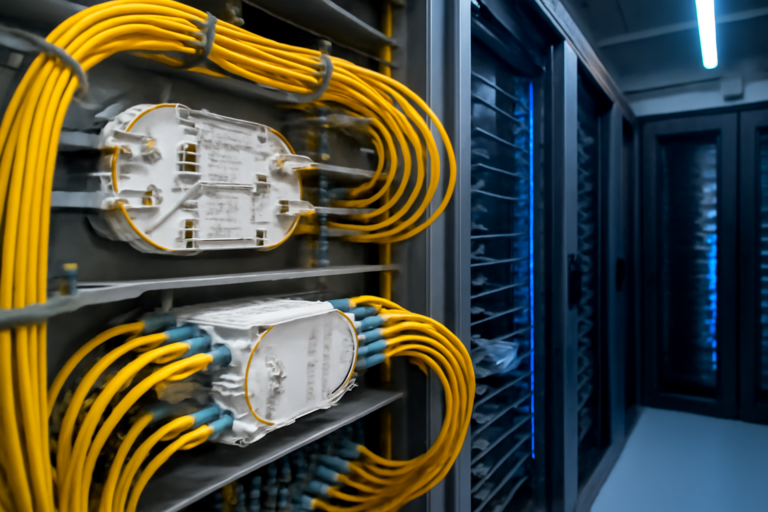
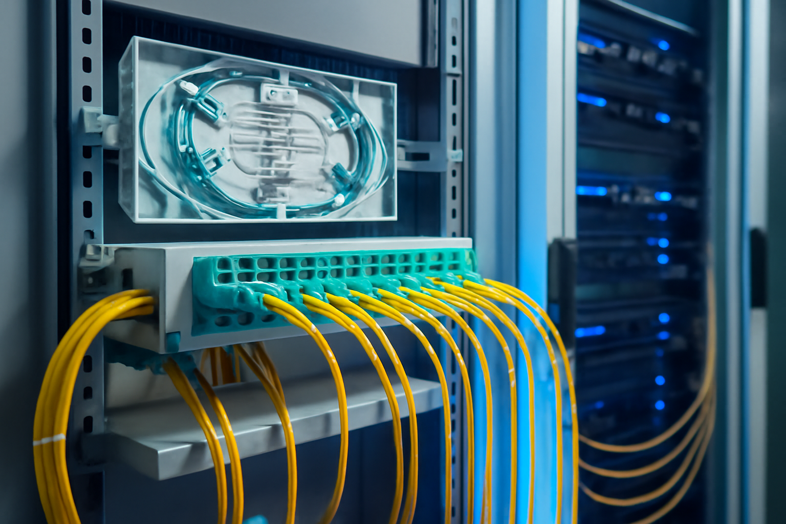
Splice distribution is performed in high-density 19-inch systems with up to 96 fibres in 1RU to optimally utilise limited space in technical rooms. Each fibre is terminated with E2000 connectors for emergency services to achieve return loss values of > 65 dB.
Fibre Splicing Technology for Control Centre Backbone
The backbone of a modern control centre is based on continuous singlemode cabling with structured splice distribution. Main distribution frames use modular splice boxes with 24 or 48 fibres per splice cassette, enabling clear fibre management and rapid fault diagnosis.
- Fusion splices with < 0.02 dB loss per IEC 61300-3-4
- Colour coding per DIN VDE 0888 for unambiguous fibre identification
- Cable strain relief with 1500 N tensile strength
- Bend radius management with R > 30 mm for long-term stability
- OTDR test protocol for every route per IEC 61280-4-2
Migration of Existing Control Centres to Modern Fibre Networks
Gradual migration from copper-based to fibre-based emergency call networks requires careful planning. During the transition phase, both systems must operate in parallel – the legacy GSM infrastructure as fallback and the new IP-based fibre connection as the primary system.
The migration path comprises three phases:
- Phase 1: Installation of fibre entry point and splice box in technical room
- Phase 2: Build-out of parallel IP infrastructure with media converters
- Phase 3: Stepwise service migration with rollback option
Fibre Products Quality Promise: As an official Diamond Partner and manufacturer, we produce modular splice systems in Europe. Benefit from Swiss precision and 5 years warranty on our systems.
Normative Requirements for Control Centre Fibre Networking
Installation of fibre infrastructure in control centres is subject to strict normative requirements. Following the Telecommunications Act Amendment 2026, fibre rollout to government facilities is classified as “of overriding public interest”, enabling accelerated permitting procedures.
| Standard | Scope | Core Requirement |
|---|---|---|
| DIN EN 50173-6 | Distributed Building Services | Structured cabling for emergency services |
| DIN EN 50174 | Installation | Grounding, equipotential bonding, fire safety |
| IEC 61754-15 | LC Connectors | Insertion loss < 0.25 dB |
| BSI Baseline Protection | IT Security | Physical access control |
Splice Box Sizing for Different Control Centre Scales
Selection of the correct splice box capacity depends on control centre size and expected data growth. Small control centres with up to 50 workstations can be served by 1RU systems, while large centres require modular 3RU or 4RU solutions.
- Small control centres: 1RU splice box with 48 fibres, LC duplex couplings
- Medium control centres: 1RU system with 96 fibres, mixed connector types
- Large regional centres: 3RU/4RU with up to 288 fibres, MPO breakout
- Redundant technical rooms: Mirrored configuration at two sites
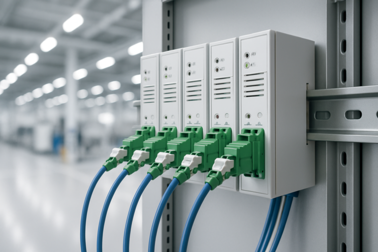
For remote site interconnection, DIN rail-mounted boxes with IP65 rating are suitable, operating reliably even in non-climate-controlled technical cabinets.
Bandwidth Requirements from New Emergency Call Technologies
With the introduction of NG eCall and expanded multimedia services, bandwidth requirements in control centres are increasing dramatically. A single NG eCall with live video can require up to 10 Mbit/s – with multiple simultaneous emergency calls, requirements quickly total several gigabits.
Capacity planning must account for these services:
- Voice Communication: 64 kbit/s per channel (G.711)
- AML Location Data: 1 Mbit/s burst for GPS coordinates
- Video Streaming: 5–10 Mbit/s per HD stream
- Vehicle Telemetry: 2 Mbit/s continuous data stream
- Hospital Interconnection: 100 Mbit/s for patient data
Quality Assurance and Test Equipment for Emergency Control Centre Fibre
Acceptance testing of emergency control centre fibre installations requires comprehensive measurements per IEC 61280. Each fibre is measured bidirectionally with an OTDR, and attenuation values are documented. Required limits are < 0.35 dB/km for link attenuation and < 0.10 dB per splice point.
The test protocol includes:
- Attenuation measurement at 1310 nm and 1550 nm
- OTDR backscatter trace with event analysis
- Chromatic dispersion for spans > 10 km
- Polarisation Mode Dispersion (PMD) for 10G Ethernet
- End-face inspection per IEC 61300-3-35
Integration with Existing Emergency Services Digital Radio Networks
Fibre interconnection of control centres must integrate seamlessly with BOS networks fibre optic. The interface between TETRA base stations and IP backbone is via specialised gateways ensuring end-to-end encryption.
Modern 1RU splice boxes with high packing density enable space-efficient integration into existing 19-inch racks adjacent to radio equipment. Modular design allows future expansion without service interruption.
Future-Proofing Through Scalable Fibre Architecture
Investment in future-ready emergency call network infrastructure pays long-term dividends. With singlemode fibres of OS2 category, transmission rates of 400 Gbit/s and beyond are possible – ample reserve for coming technologies such as 5G backhaul or quantum communications.
- Preparation for Real Time Text (RTT) from 2027
- Integration of AI-driven emergency call analysis
- Drone live-image interconnection
- Smart city infrastructure networking
- 5 year warranty on modular splice systems for investment security
Practical Implementation: From Planning to Commissioning
Realisation of high-availability emergency control centre fibre interconnection follows a structured project workflow. Following requirements analysis and cable route planning, splice distribution installation and subsequent quality assurance are executed.
| Project Phase | Duration | Key Activities |
|---|---|---|
| Requirements Analysis | 2 weeks | Bandwidth, redundancy, growth planning |
| Cable Route Planning | 4 weeks | Civil works, permits, coordination |
| Installation | 3 weeks | Cable pulling, splicing, termination |
| Acceptance | 1 week | OTDR measurement, documentation |
| Migration | 2 weeks | Stepwise service migration |
As manufacturer of modular fibre solutions and official Diamond Partner, Fibre Products provides the complete system solution for control centres – from the compact 1RU splice box to the high-density VarioConnect system with Swiss precision quality. Our extended 5-year warranty protects your investment long-term.
Frequently Asked Questions on Emergency Control Centre Fibre Networking
What fibre density does a medium-sized control centre require?
A control centre with 30–50 workstations typically requires 48 to 96 fibres in the backbone. Two fibres (duplex) per workstation plus 50% reserve should be planned. Modern 1RU splice boxes offer up to 96 fibres in just one rack unit.
How is fault tolerance ensured if a fibre is cut?
Through redundant cable routing with physically separate paths and automatic failover in < 50 ms. Additionally, critical connections are routed via two different network operators to prevent total outage.
Which connector types are suitable for control centre environments?
For maximum reliability, LC-APC or E2000-APC connectors with protective shutters are recommended. These offer return loss > 65 dB and are dust-resistant. MPO connectors are used for high-density cabling.
How is migration from copper to fibre accomplished without service interruption?
Through parallel build-out of fibre infrastructure and stepwise migration of individual services. Media converters enable temporary legacy system interconnection. A detailed rollback plan secures emergency operation.
Which measurements are critical during acceptance testing of control centre cabling?
Key values are total attenuation < 0.35 dB/km, splice loss < 0.10 dB and connector loss < 0.25 dB. Return loss must exceed 65 dB. All values are measured bidirectionally per IEC 61280-4-2.
How much bandwidth does the new NG eCall technology require?
An NG eCall with HD video and telemetry data requires 5–10 Mbit/s per connection. With 10 simultaneous emergency calls with multimedia, at least 100 Mbit/s symmetrical should be available, preferably 1 Gbit/s for peak loads.
Request a Quote
Do you have questions about our fibre solutions? Our expert team will be happy to advise you – free and with no obligation.